![]() Motor control is a topic that engineers cannot avoid. Qualified engineers must have rich experience in the entire motor control before designing. This article details the process and composition of motor control from the three aspects of synchronization, timing and software, and shares the experience of engineers in practical work.
Motor control is a topic that engineers cannot avoid. Qualified engineers must have rich experience in the entire motor control before designing. This article details the process and composition of motor control from the three aspects of synchronization, timing and software, and shares the experience of engineers in practical work.
Synchronization and timingThe first priority for every real-time application is proper timing, synchronization, and deterministic system response, and special attention must be paid to these aspects when designing motor control software. In essence, the process sounds very simple: the system reads sensor values, processes the control algorithm, monitors system safety and manages the output stage by adjusting the duty cycle of the PWM output.Small timing errors can lead to severe system response errors, operational instability, and poor performance. To ensure that everything is running as expected, it is crucial to stay in sync and ensure the determinism of the system. What I want to emphasize here is that we are dealing with a "hard real-time system" and meeting tight deadlines is absolutely crucial.The motor controller software can be implemented as a bare-metal solution without an operating system using a suitable RTOS (real-time operating system), or as a multi-core hybrid solution where some CPU cores run in bare-metal mode while others use a operating system. Bare metal solutions have always been based on interrupt-driven design, where interrupts handle time-critical tasks, ensuring everything happens at precise intervals.Whether it is a bare metal, RTOS or hybrid solution, timing analysis, task prioritization and safety analysis must be performed to ensure efficient and reliable system performance.Timing analysis ensures that all tasks are completed on time. This includes considering the worst-case execution time of each task. Some of the major critical tasks in motor control include sensor data acquisition, execution of control algorithms through PWM signal generation, fault detection and handling, emergency stop and safety functions, real-time communication with other system components, and synchronization with external systems.As mentioned earlier, phase-locked loops (PLLs), whether integrated into MCU/DSP hardware or implemented as IP cores in FPGAs, are critical for synchronizing critical events. The main function of the PLL is to synchronize the internal clock of the MCU/DSP/FPGA with an external clock source or signal. This is critical to maintaining timing accuracy in real-time applications. PLLs help reduce clock jitter, which is critical for precise timing, especially when controlling the speed and position of motors. The PLL ensures precise timing alignment between feedback signal sampling (such as rotor position and current measurements) and control algorithm execution, ensuring optimal synchronization and accuracy. In multi-core systems, a PLL can be used to synchronize the operation of these cores.Synchronizing pulse-width modulation (PWM) with current measurement and analog-to-digital conversion (ADC) through a phase-locked loop (PLL) is critical to ensuring accurate and efficient system performance in motor control applications. With synchronous clocks, the PLL ensures that all system components, including PWM generators, ADCs, and other processing elements, run on synchronous clocks. The PWM signal that controls the power delivered to the motor is generated based on this synchronized clock. The timing of these signals directly affects motor performance. The current sensor measures the current flowing through the motor. The timing of these measurements is critical, especially in systems such as field-oriented control (FOC), where current feedback is used to control motor torque and speed. Use an ADC to convert the analog signal of the current sensor into a digital value. The PLL helps synchronize the ADC sampling with the PWM period. This synchronization ensures that the ADC samples the current at the optimal time relative to the PWM signal (usually at the point where the PWM is neither fully on nor fully off) to obtain an accurate current. The digitized current measurements are then fed into the control algorithm. The PLL ensures that measurements are taken at consistent intervals relative to the PWM signal, allowing the control algorithm to accurately modify the PWM duty cycle based on changes in state variables, ensuring optimal motor performance. By synchronizing the ADC sampling with the PWM, the effects of switching noise and distortion can be minimized. This is especially important in high-power motor control applications, where the PWM signal can generate significant noise.
Current and position measurements
It is critical to accurately measure the current and synchronize it with the PWM pulses. Use techniques such as periodic sampling, current oversampling, and averaging to improve accuracy.The periodic sampling frequency is the same as the PWM frequency, so the challenge is to determine the appropriate sampling time. This involves setting an appropriate delay between the start of the PWM period and the analog-to-digital conversion.Current oversampling involves sampling at a frequency higher than the PWM frequency (sometimes 8-32 times higher) and averaging the measurements. The ADC Interrupt Service Routine (ISR) frequency can be much higher than the PWM frequency, allowing detailed data to be collected.Oversampling is limited by the bandwidth of the current sensor. For example, most Hall sensors commonly used for motor control have bandwidths between 50 kHz and 160 kHz. Correct timing and synchronization are key to dealing with high frequency oscillations affecting phase currents.
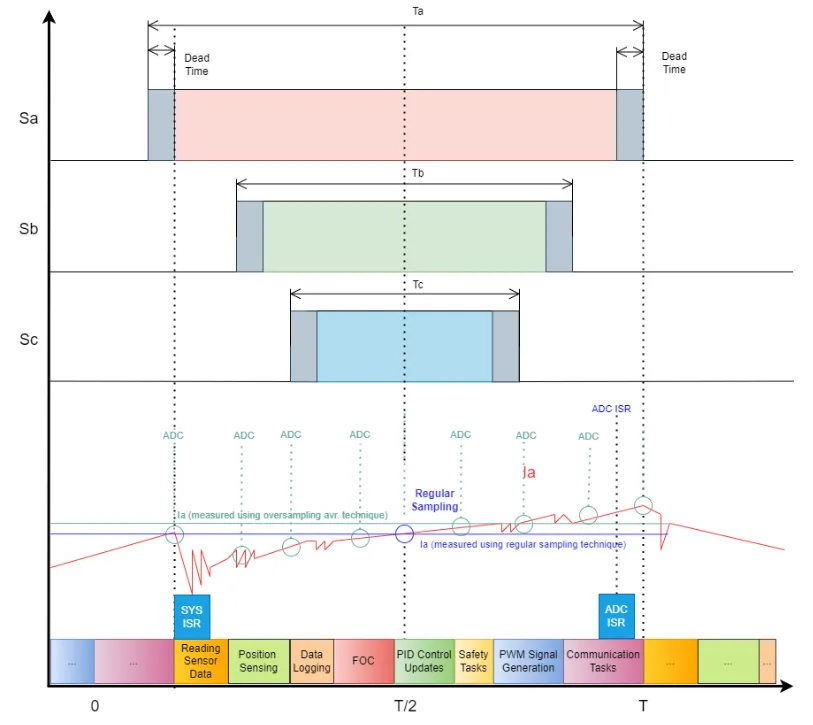
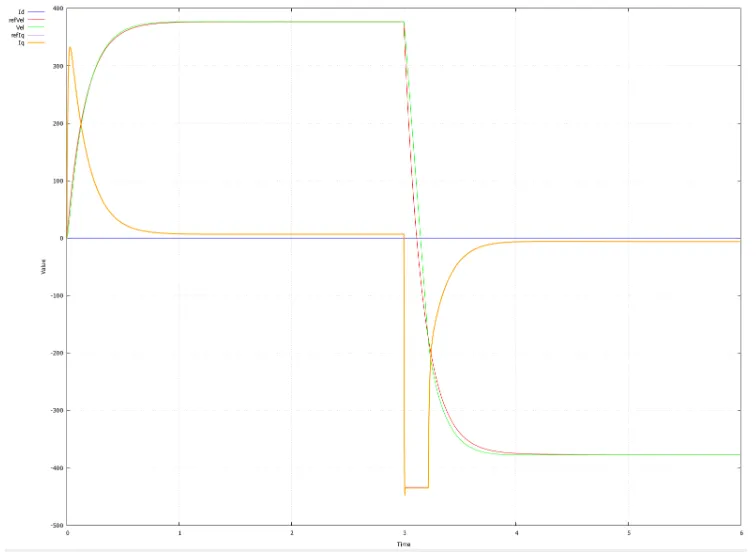
Figure 1: Synchronized PWM and current measurement
Figure 1 shows the timing during a processing cycle. Analog-to-digital converters (ADCs) can be configured for high-frequency sampling. This requires setting the ADC clock and adjusting its sample rate. After sampling is complete, the MCU or DSP processes the samples to calculate their average. This calculation is usually performed after accumulating a specific number of samples. The main processing interrupt service routine (ISR) must be configured to trigger when the averaging calculation is completed. Additionally, the PWM module needs to be set up in a way that ensures synchronization between ADC sampling, ISR and PWM timing. Modern MCUs and DSPs excel at handling these tasks simultaneously, thanks to their processing power, real-time operation capabilities, and various peripherals designed to manage ADC, PWM, and ISR tasks.It is critical that the sampling of position sensor data is synchronized with the main processing interrupt service routine. Any delays caused by data transfer are also taken into account and can be calculated to maintain timing accuracy. When applying any filter, it is important to consider the effect of phase delay. In the case of using a resolver to measure angular velocity, the processing of the resolver data must be synchronized, and the points with the smallest amplitudes of the sine and cosine signals must be selected to ensure accurate readings. Additionally, the resolver signal is oversampled and a bandpass filter with a cutoff frequency matching the PWM frequency is applied. This approach helps filter out unwanted frequencies while maintaining signal integrity.In high-speed systems, position must be inferred to ensure accuracy of the rotor so that the stator magnetic field is correctly aligned relative to the rotor magnetic field. Precise angle measurement ensures the right amount of power is delivered to the motor at any given time, reducing energy loss, torque ripple, vibration and heat generation.This discussion focuses on field-oriented control (FOC) applications utilizing direct rotor position measurement. It does not delve into sensorless FOC applications since the rotor position is not directly measured but estimated through indirect methods.Some common safety features commonly found in motor control applications include:Safe Torque Off (STO): This feature immediately cuts power to the motor driver, causing the motor to stop producing torque. This is a vital feature in emergency situations when the motor needs to be stopped as quickly as possible to prevent injury.Safe Direction (SDI): Prevents the motor from running in an unexpected direction.Safe Operating Stop (SOS): This feature keeps the motor in a stopped state without cutting off power.Safe speed range (SSR) or safe limited speed (SLS): Ensures that the motor operates within a safe speed range or below the safe maximum speed.Overcurrent protection: This feature protects motors and electronic equipment from overcurrent damage caused by faults such as short circuits or overloads.Overvoltage and undervoltage protection: These features prevent voltages that are too high or too low, which could damage the motor or control electronics.Thermal Protection: Monitors the temperature of the motor and drive and if the temperature exceeds safe limits, the system can shut down to prevent overheating.Speed Monitoring and Limiting: Ensures that the motor does not exceed predefined speed limits, which is critical in applications where exceeding a specific speed could be dangerous.Emergency Stop: A physical button or switch that stops the motor immediately. This is a must-have standard feature in industrial applications.Safe Brake Control: For brake-equipped motors, this feature safely engages the brake to stop the motor, especially in applications where gravity will cause vertical movement. Before activating the safe braking function, the system first attempts to stop the motor using electrical braking (if possible), during which the energy flow is reversed to slow down the motor.Security functions can be implemented in hardware (HW), software (SW), or a combination of both, depending on the specific requirements and constraints of the application. Safety features such as over- and under-voltage protection, over-current protection, thermal protection, and emergency stop are often implemented in hardware to ensure strong, fast, and reliable system protection.Speed monitoring and limiting, fault detection algorithms and Safe Operating Stop (SOS) are implemented in software.Functions such as Safe Torque Off (STO), Safe Direction (SDI), Safe Speed Range (SSR)/Safely Limited Speed (SLS) and Safe Brake Control are typically implemented through a combination of hardware and software. This hybrid approach typically involves software commands for initiation and control, while relying on hardware components for efficient execution and execution.The topic of safe design and functional safety in motor control (including standards such as SIL3) is another specialized topic.Various manufacturers in the embedded systems and motor control space offer comprehensive design packages and tools designed to facilitate and accelerate the design and certification process in key sectors such as industry, transportation, energy and medical. These software packages typically include pre-certified software libraries, detailed safety manuals, and hardware modules designed to comply with strict safety standards such as IEC 61508, ISO 13849, and others. In addition, they often provide extensive documentation and support to achieve certifications such as SIL (Safety Integrity Level) ratings, which are critical for high reliability and safety-critical applications. This assistance not only streamlines the development process, but also significantly reduces the time and effort required for compliance and certification in these highly regulated industries.
Real-time operating system (RTOS)
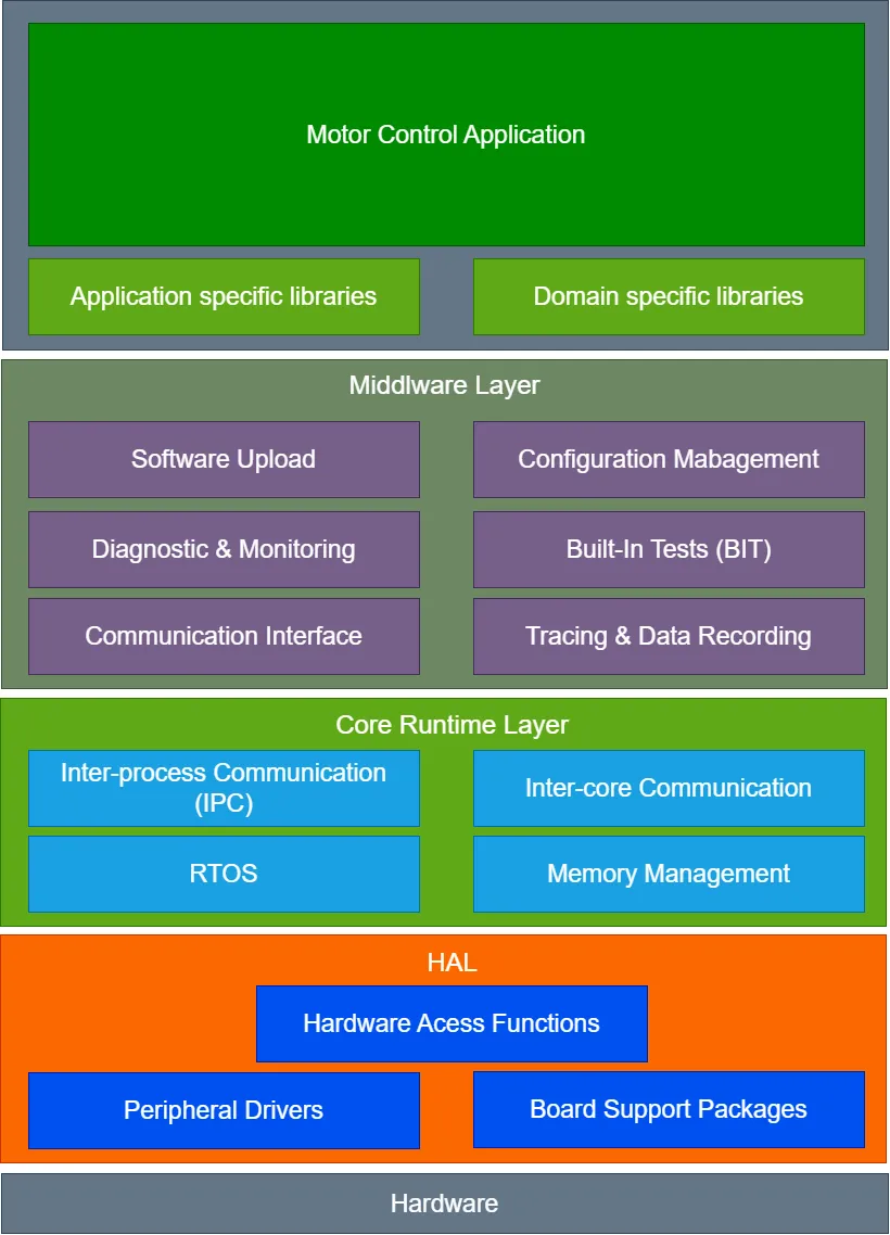
Choosing the right RTOS for your motor control application is critical to ensuring high performance, reliability, and safety. Key considerations include RTOS real-time performance, resource efficiency (including memory footprint and CPU usage), and priority-based preemptive scheduling processing. Efficient and fast outages as well as system reliability and robustness are also key factors. Vendor support and documentation, compatibility with hardware, and the availability of development tools (such as IDEs, debuggers, and profilers) and ecosystem (including libraries and code samples) play an important role. Finally, the licensing terms and cost of the RTOS should also be considered.Taking into account the various factors and specific requirements of a motor control application, FreeRTOS, the acclaimed open source real-time operating system known for its efficiency and versatility, becomes an excellent choice. This option is particularly beneficial in scenarios where cost-effectiveness, operational efficiency, system flexibility, reliability and robustness, ease of use, broad hardware support and resource efficiency are key considerations.Figure 2: Motor control system architecture overviewThe architecture of a motor control application consists of multiple layers and modules:Hardware Abstraction Layer (HAL): Provides standardized interfaces for accessing hardware peripherals, including ADCs, PWM controllers, and communication interfaces, promoting portability and scalability. It also contains Board Support Packages (BSP) and drivers for various hardware peripherals, enabling seamless hardware-software integration.Core real-time operation layer: This layer contains the real-time operating system (RTOS) for efficient task scheduling and system resource management. It also includes specialized memory management, with a real-time heap allocator designed to optimize memory allocation in time-critical applications. Additionally, this layer integrates powerful inter-core and inter-process communication (IPC) mechanisms to facilitate seamless data exchange and synchronization between different cores and processes within the system. This layer serves as the backbone of core operational functionality, ensuring smooth and efficient runtime performance.Middleware layer: This layer integrates the following key functions:
-
Communication interfaces: Manage interactions with external systems or devices using various communication protocols.
-
Tracking and data logging: Focus on tracking and recording specific signals and events, with the ability to output data in real time through DAC, IO, Ethernet, UART, USB and other channels.
-
Software Upload: Oversee the upload of new software versions or updates to ensure seamless integration and system continuity.
-
Configuration Management: Handles customers' system configuration settings optimization and operational adjustments.
-
Diagnostics and Monitoring: Provides system diagnostics and ongoing monitoring tools that are critical to maintaining system health and performance.
-
Built-in Test (BIT): Includes self-test capabilities to check the status and functionality of hardware and software components.
Motor Control Application Layer: At the top of all layers is the motor control application, which is a key component for executing application-specific workflows. This layer encapsulates:
-
Control and signal processing algorithms: This includes core control algorithms such as PID control and field-oriented control (FOC), as well as signal processing algorithms designed to optimize motor performance.
-
Safety Logic: This component works on the safety aspects of the system, implementing necessary protocols for emergencies and routine safety checks to ensure the system operates within safety parameters.
-
Application-specific workflows: This layer also integrates additional, unique workflows tailored to the specific requirements of the motor control application, ensuring comprehensive functionality and performance.
Application workflows typically involve several key steps:First-stage boot loader (FSBL): This important component is responsible for the initial stages of the boot process, including low-level hardware initialization and loading of major software components. A key part of its role is to load and start user applications. FSBL runs separately from the application layer and is usually provided by the MCU or DSP in its SDK. Customizing the BSP, such as adding additional memory checks or diagnostic capabilities, is often required to ensure that the FSBL meets specific system requirements and enhance overall reliability.Platform setup: Initialization of hardware components: This includes setting up the ADC (Analog-to-Digital Converter), system interrupts, PWM (Pulse Width Modulation) module, communication interfaces (such as SPI, I2C, UART), watchdog timer and any other necessary hardware peripherals. Set up interrupt handling mechanisms to respond to events such as timer overflow/input change or communication. Configure system clocks, power modes, and ensure efficient power management of controllers and motors.Application Configuration: This step contains the critical task of defining operating parameters, which is typically accomplished by reading a configuration file. These files specify basic details such as motor characteristics, control parameters, and operating limits. Additionally, configuration settings can be adjusted in a variety of ways, including digital inputs, DIP switches, or dynamically via an external PC or host device's communication interface. This multifaceted approach ensures flexible and adaptable configuration management that meets a wide range of application needs.This stage also includes:
-
Define tasks: Create tasks such as master control tasks, communication tasks, health monitoring tasks, etc. that are critical to the functionality of the application.
-
Set Priority: Assign priorities to these tasks based on their importance and role in the application. This is critical to ensure that critical tasks (such as the main control task) receive the necessary CPU response than less critical tasks.
-
Configure task properties: This can include setting the stack size, specifying task parameters, and configuring any task-specific properties.
-
Establish inter-task communication: Establish mechanisms for inter-task communication, such as queues, semaphores, or shared data structures.
Sensor Calibration: In applications where sensors are integrated, their calibration is critical to ensuring the accuracy of the readings. Specifically, commonly used Hall effect sensors exhibit an initial offset that must be taken into account. During the calibration phase, these initial offsets are identified and subsequently subtracted from the current measurements to correct the sensor output. This step is critical to ensure the accuracy of the sensor data.Communications and Monitoring: Handles communication with external devices or systems for command and control, diagnostics, or remote monitoring.
Human Machine Interface (HMI)
In motor control applications, HMI can represent simple physical controls and indicators (such as buttons, LEDs, or displays) or remote control interfaces.This part of the workflow includes:Sensor data acquisition: Reading and processing data from sensors in real time, necessary for control loop feedback.
-
Real-time control loop execution: This is where the main control algorithm (such as PID control or FOC) is executed, usually in the main controller. Respond to timer interrupts for consistent timing.
-
Actuator command generation: Generate commands for actuators such as motor drivers based on the output of the control algorithm. It usually involves setting up specific digital outputs and PWM signal generation.
-
Safety and emergency handling: To ensure immediate response to safety and emergency incidents (such as emergency stops), these incidents should be handled sequentially and with high priority during this dedicated phase. This approach not only minimizes delays in processing critical events, but also enhances the overall security and reliability of the system. Additionally, this phase includes detecting and responding to various types of faults, including overcurrent, overvoltage, and hardware faults. By prioritizing these tasks, the system is better able to address and mitigate potential risks in a timely manner, ensuring a safer operating environment.
The key principle is to maintain a concise Interrupt Service Routine (ISR), primarily used to notify the main control task when further processing is required. Its main role is not to execute the entire control logic within the ISR, but to notify higher-priority tasks about the occurrence of events. For this purpose, FreeRTOS provides various notification methods, such as binary semaphores, task notifications, or queues. The main control task is an RTOS task responsible for the main control algorithm. Once the ISR notification is received, the task is activated (or unlocked) and performs all necessary steps described previously. It is crucial to assign appropriate priorities to the main control tasks to ensure that the control algorithm processes them promptly after the ISR.A watchdog timer should be used to ensure the running of a main task that is designed to periodically reset the watchdog timer, demonstrate its correct operation and prevent the timer from expiring and triggering a system reset or error routine.System health monitoring: Continuously monitor the system for faults such as overheating or other anomalies, and take appropriate action if any issues are detected.Logging and data logging: Record important events, errors, and system performance metrics for future analysis or troubleshooting.Figure 3: Data Journey: From Motor Controller Logging to PC AnalysisGraceful shutdown: Ensures that the motor and controller shut down safely when the application is stopped.If the application runs on a multi-core MCU/DSP/FPGA, appropriate inter-core communication mechanisms must be ensured. This can be accomplished using on-chip shared RAM and software interrupts, but the method may vary depending on the platform. Other possibilities include message passing interfaces, direct memory access (DMA) channels, or the use of architecture-specific dedicated hardware communication blocks.A common approach is to have one core dedicated to communication tasks and another core to the main control loop. An RTOS is typically used on both cores for efficient task management, but the main control core typically runs in a bare-metal environment for simplified low-level control. Including CLA from Texas Instruments (TI), ARM's Cortex-M DSP extension, STMicroelectronics' ART accelerator, Microchip's dsPIC, NXP's motor control coprocessor and Infineon's XMC digital protocol Processors provide specialized processing units to enhance the performance of specific embedded system applications. Such scaling increases overall computing bandwidth and frees the CPU to perform other tasks such as communications, monitoring, and diagnostics.The author of this article: Boris Radonic is a R&D engineer with more than 30 years of experience in electronic engineering, control systems and software engineering, focusing on real-time applications. He holds an engineering degree from the University of Zagreb and a master's degree from the University of Applied Sciences and Arts in Northwestern Switzerland.


 XINDA
XINDA