Stepper Motor Driver Design Reference Guide
A stepper motor , as the name suggests, is a motor that runs step by step.
According to the structure of stepper motor, it can be divided into three types: permanent magnet type, reactive type and hybrid type.
There is more than one type of stepper motor, and one type of stepper motor has two windings. The two windings are on the stator, and the rotor is a permanent magnet.
The essence of all motors is the same. Electromagnets attract permanent magnets (or electromagnets) and achieve the function of rotation through sophisticated mechanical design. Of course, there are also linear motors that perform linear motion or vibration motors that perform reciprocating motion.
We will leave aside the structure of the motor itself and only explain the principle.
The rotor and stator frames of the stepper motor are both made of stacked silicon steel sheets with high magnetic permeability .
A stepper motor has a step angle, say 1.8 degrees.
The basic operating logic of the stepper motor is: energize the winding, energize in the forward direction, energize in the reverse direction, and not energize.
Each winding has three states, and the states of two windings are 2*3=6.
There are three driving modes for stepper motors, namely full-step, half-step and micro-step driving.
According to the number of energized phases, full-step drive is divided into single-phase full-step drive (one winding is energized at a time) and two-phase full-step drive (two windings are energized at a time).
The rotation logic of the stepper motor is to switch between various power-on states to achieve the rotation of the magnetic field, thereby driving the rotation of the motor.
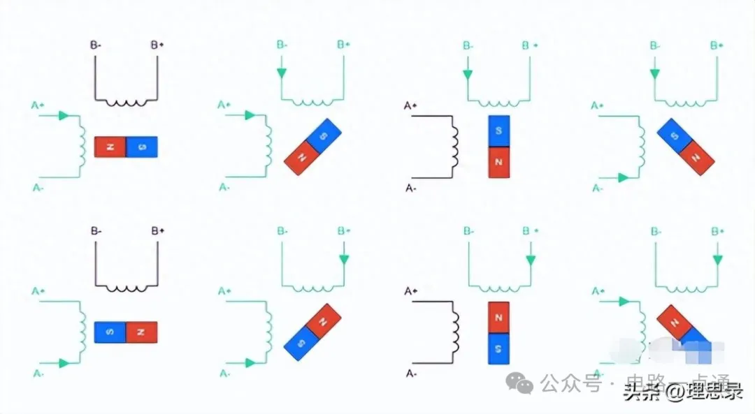
To describe the windings, we name the two windings A winding and B winding respectively.
The two ends of the winding are A1, A2, B1, B2
A1 is connected to positive voltage, A2 is connected to negative voltage: recorded as A1->A2 to form magnetic field NA
A2 is connected to positive voltage, A1 is connected to negative voltage: recorded as A2->A1 to form magnetic field SA
B1 is connected to positive voltage, B2 is connected to negative voltage: recorded as B1->B2 to form magnetic field NB
B2 is connected to positive voltage, B1 is connected to negative voltage: recorded as B2->B1 to form magnetic field SB
The two poles of the coil are not connected to the power supply, or are connected to the positive or negative power supply at the same time A1-A2 B1-B2
The law of vector composition is a universal law, which is the parallelogram law .
|
A winding is not energized Winding is non-magnetic A1-A2 |
Winding B is not energized Winding is non-magnetic B1-B2 |
The motor has no damping and does not move. |
|
Forming magnetic field NA A1->A2 |
Winding B is not energized Winding is non-magnetic B1-B2 |
Magnetic field NA is coupled with the rotor magnetic field
|
|
A1-A2 |
B1-B2 |
|
|
A1-A2 |
B1-B2 |
|
|
|
|
|
|
|
|
|
The commonly used hybrid stepper motor has a step angle of 1.8 degrees, the rotor has 50 teeth, and the stator has only 48 teeth, which are divided into 8 main poles. If these 8 main poles are divided into 4 pairs, we will find that the teeth of one pair of stators and rotors are completely aligned, the teeth of one pair of stators and rotors are misaligned, and the teeth of the other two groups of stators and rotors are half-aligned.
The magnetic field structure of the stepper motor rotor is different from what is usually imagined intuitively.
A step angle of 1.8 degrees does not necessarily mean that there is a change in the NS pole of the magnetic field every 1.8 degrees.
Instead, the tooth difference between the transmission and the rotor is customized to achieve magnetic field matching every 1.8 degrees.
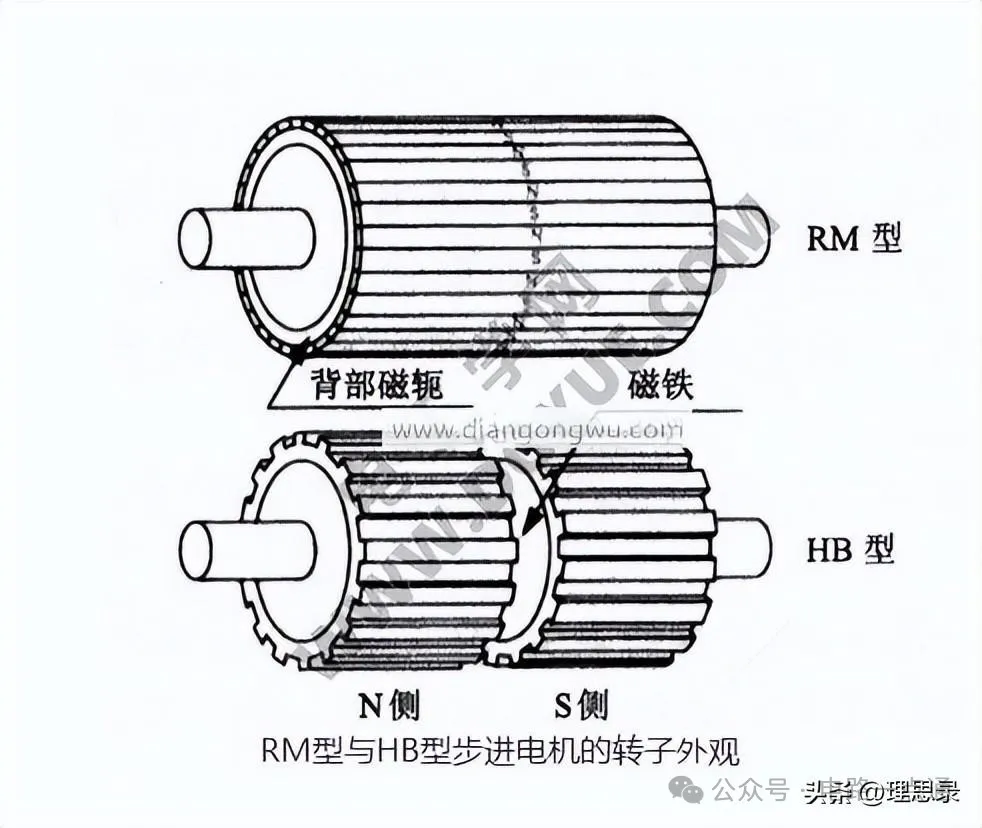
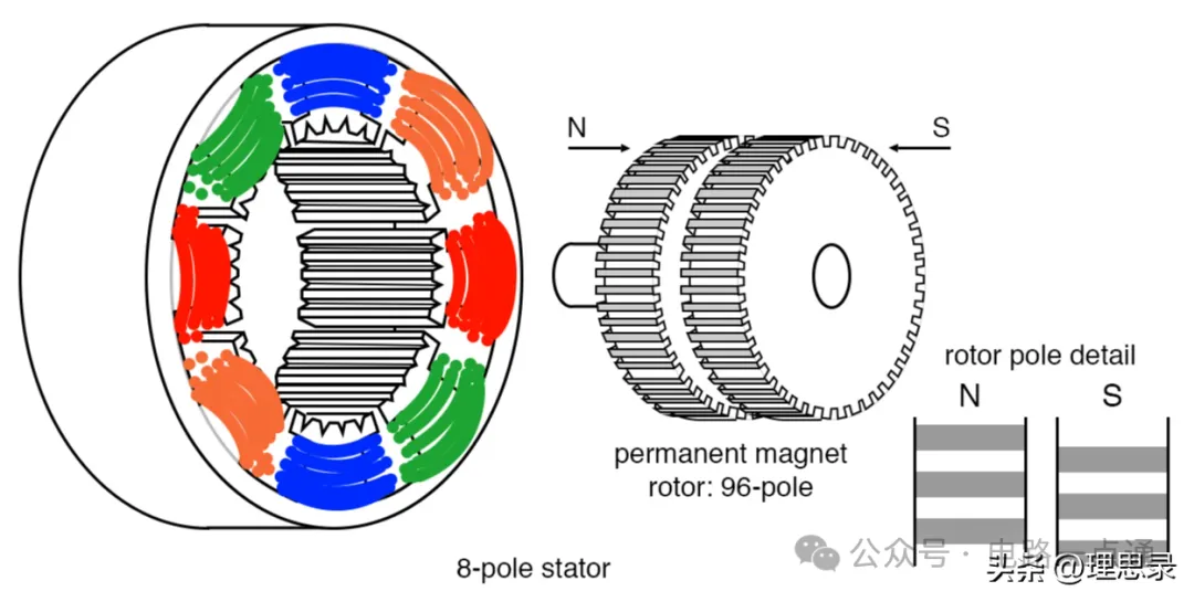
When a pulse signal is given to the stator, the stator magnetic field changes, and the rotor moves slightly to align with the stator teeth. In the full drive case, each movement is half of a concave or convex tooth, and the angle is 1.8 degrees.
If it is half-step drive, this angle will be further reduced to 0.9 degrees.
General driving principle:
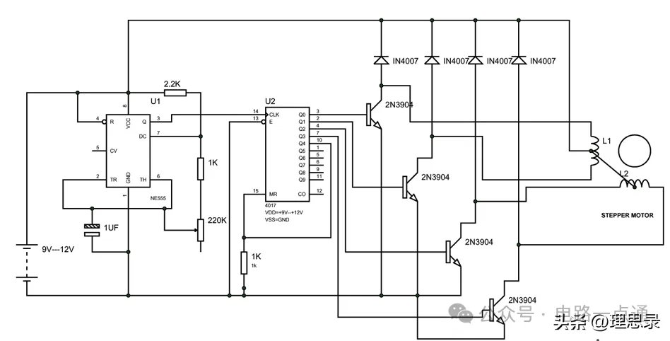
There are three step angles for different motor phases: 1.80 (two-phase), 1.20 (three-phase), 0.72° (five-phase)
The stator of the two-phase hybrid stepper motor has 8 large teeth, 40 small teeth, and the rotor has 50 small teeth;
The stator of a three-phase motor has 9 large teeth, 45 small teeth, and the rotor has 50 small teeth.
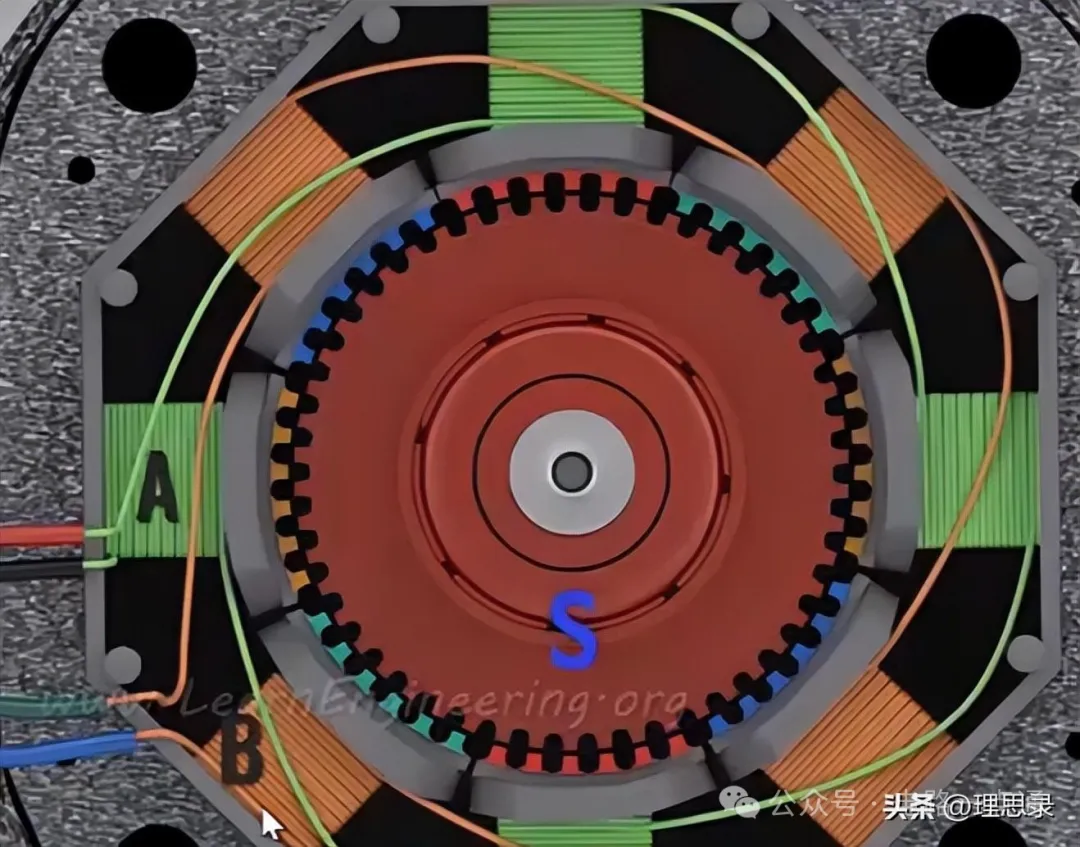
There are 8 large teeth on the stator, each of which consists of 6 small teeth.
There are 48 small teeth on the rotor.








 XINDA
XINDA