


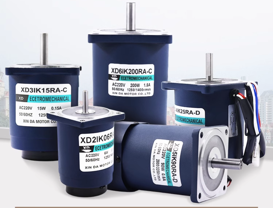


Assembly process of small and medium-sized motors
01
stator assembly
In China, most motor manufacturers use external press-fitting technology when producing small motors. After the stator core is wound and impregnated, its axial position must meet the drawing requirements when pressed into the frame. Otherwise, one end of the coil will extend too far, causing assembly difficulties and increasing the air gap magnetomotive force, affecting motor performance. It will also exacerbate wear caused by the axial force on the rotor. The axial position of the stator core within the frame is generally ensured by the press-fitting fixture. The dimensions of the press cap are controlled to ensure that the position of the core conforms to the drawing requirements after press-fitting.
The method for determining the size is as follows: after the press-fitting is completed, in order to ensure that the stator core does not rotate in the frame, the contact between the inner circle of the frame and the outer circle of the stator core is not enough. Therefore, each motor must also be equipped with a locking screw to completely fix the core to the frame.
02
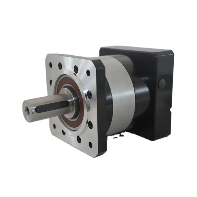
Rotor assembly
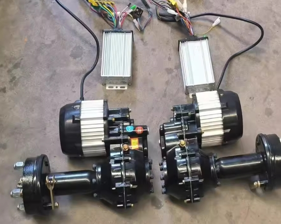
The rotor assembly of an asynchronous motor includes the assembly of the rotor core and shaft, the assembly of bearings, and the assembly of the fan.
1
Assembly of rotor core and shaft
Electric motors output mechanical power through their shafts during operation; therefore, the reliability of the rotor core-shaft connection is crucial. When the rotor's outer diameter is less than 300mm, the rotor core is typically press-fitted directly onto the shaft. When the rotor's outer diameter is greater than 300mm to 400mm, the rotor support is first press-fitted into the core, and then the shaft is press-fitted into the rotor support. Y-series motors employ a structure where the rotor core is directly press-fitted onto the shaft. There are three basic assembly methods for the rotor core and shaft: knurled cold-press fit, heat-fit fit, and keyed connection fit.
In a knurled cold press fit, the shaft machining process is as follows: precision turning of the core retaining ring, knurling, grinding, then pressing in the rotor core, followed by precision grinding of the shaft extension and bearing retaining ring, and precision turning of the core outer diameter. Excessive interference is not permitted when using the knurling process. This is because the cold pressing pressure is directly proportional to the interference; if the interference is too large, it may not be able to be pressed in, or it may cause excessive internal stress in the material, leading to deformation or damage.
Hot-fitting typically utilizes the residual heat from the rotor's aluminum casting process (or reheating the rotor) for hot fitting. This process saves on cold-pressing equipment and ensures a more reliable connection between the rotor core and shaft. Because hot fitting involves heating and expanding the housing, followed by cooling, the housing's opening contracts to grip the enclosed component, guaranteeing sufficient interference fit and high reliability.
Keyed connections offer the advantage of reliable connection and facilitate streamlined production; however, they increase machining steps, and keyways on the shaft reduce its strength, especially in small motors. When using keyed connections, the key width is selected according to specifications. To simplify the process, the same keyway width as the shaft extension can usually be used.
2
Bearing assembly
Rolling bearings are widely used in small and medium-sized asynchronous motors. They are lighter than sliding bearings, require less maintenance during operation, and consume less lubricating grease. Furthermore, rolling bearings have small radial clearance, making them more suitable for asynchronous motors with small air gaps.
03
General Assembly
The final assembly of small and medium-sized motors includes fitting the rotor into the stator, installing other components such as end covers, junction boxes, external fans, and brush devices. After final assembly, testing and surface finishing of the motor are also required.
1
Rotor fitting into stator assembly
Inserting the rotor into the stator is a crucial step. Improper operation can easily damage the windings, and sometimes even deform the shaft. When inserting the rotor, attention must be paid to the corresponding position of the shaft extension and the junction box. For rotors weighing less than 35kg, they can be inserted into the stator by hand. Larger rotors require lifting tools. During operation, first lift the tool at lifting ring 2 and place it on the rotor shaft. Then, lift the rotor at lifting ring 1 and use the control lever 3 to guide the rotor horizontally and smoothly into the stator.
2
Install end cap
When installing end covers, generally install the non-shaft extension end first. Apply a thin layer of machine oil to the mounting surface to prevent rust. After inserting the end cover into the mounting surface, gently tap around the end cover to ensure it fits snugly against the machine base. Then, tighten the bolts diagonally. When installing the second end cover, the rotor needs to be leveled (this is not necessary for small motors). Then, tap the end cover mounting surface together and tighten the bolts. If the two end covers are not aligned or their end faces are not parallel, the rotor may rotate sluggishly. In this case, gently tap around the end cover with a hammer to eliminate the misalignment and ensure the rotor rotates freely. Finally, install the outer bearing cover and tighten the bearing cover screws.
3
Breathing adjustment
For medium-sized motors with rolling bearings using round end caps, after the rotor is inserted into the stator, the end caps for the ball bearings should be installed first, followed by the end caps for the roller bearings, to prevent damage to the rolling bearings. If it is necessary to install the end caps for the ball bearings first, the screws on these end caps should not be tightened until the ball bearing end cap is installed, at which point the screws are tightened. After the end caps are installed, the air gap must be adjusted. The adjustment method is to use jacks (four at both ends) to adjust the relative positions of the end caps. Use a feeler gauge to measure at a 120° difference (at both ends) until the air gap uniformity meets the technical specifications. After adjusting the air gap, tighten the screws, drill locating pin holes at the positions specified in the drawing on a horizontal punch press, and insert the locating pins.
4
Assembly of the brush system
04
Small motor assembly automation
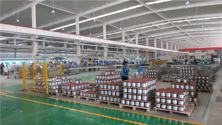
Through these computers, the FAS system can easily modify programs and control the assembly system to achieve automated assembly of motors of various specifications. For example, an automated assembly system developed abroad can automatically assemble 450 different specifications of small motors. This demonstrates that the FAS flexible assembly system not only has a high degree of automation but also strong adaptability, representing the current direction of automation in small motor assembly. In addition to assembly automation, there are also automated lines for motor factory testing and automated electrostatic painting. Using these automated lines will greatly improve working conditions and increase labor productivity, creating favorable conditions for achieving dehumanized production in motor factories.
 XINDA
XINDA