


Analysis of Wheel Hub Drive System
1. Abstract
In general, there are two urgent problems that need to be solved in promoting the widespread use of new energy electric vehicles . First, compared with ordinary internal combustion engine vehicle models, its cruising range is shorter, and second, the cost of power batteries is higher. With the advancement of scientific research and technology, these two problems are expected to be solved in the future. For example, to address range anxiety, it is not only technological advances that improve power battery performance that are important, but the ubiquitous power battery charging infrastructure. In response to these problems, the joint efforts of the government and major car companies and suppliers can realize the widespread use of new energy electric vehicles. To this end, with the aim of expanding the use of next-generation vehicles, the "Next-Generation Vehicle Strategy" has been formulated. According to the roadmap shown in the strategy, it will focus on supporting the development of infrastructure, such as the creation of "new energy electric vehicle/plug-in hybrid vehicle (EV/PHV) urbanization".
For future new energy electrification/PHEV models, the vehicles needed in towns are considered to be the following types:
1) Fixed-route buses that can run and charge regularly;
2) Delivery vehicles that are used in limited areas and can be charged late at night;
3) Short-to-medium-distance commuters (less than 40 kilometers per day) living near residences;
The service requirements of the commuter vehicle types in these three items can be met to a certain extent by small single-person commercial vehicles in the case of models equipped with large cargo compartments . However, in order to achieve widespread use of electric vehicles, it is crucial to create a market for ordinary users, not just business users. A 2009 financial survey on the use of cars with small-displacement engines showed that about half of the users used their cars primarily for shopping and transporting family members. In similar applications, demand for new energy electric commuters is also expected to be high.
With this in mind, if steps are taken to accommodate two or more passengers while maintaining the compact size of this type of vehicle, the new energy electric commuter can be a way to meet a wide variety of needs and Deliver on the promise of widespread availability. In addition, designing a vehicle for short and medium distances can reduce the weight load of the power battery, thereby reducing its cost. This paper presents an example of the development of new energy electric vehicles that reduce costs from this perspective. A commuter car where securing room for luggage and similar cargo is also important.
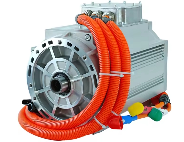
To provide driving power for new energy electric vehicles, the drive motor replaces the internal combustion engine of traditional vehicles. Compared with ordinary new energy electric vehicles that transmit power to the wheels through the transmission system, the wheeled new energy electric vehicles that install the engine on the driving wheels can increase the space for passengers and luggage without increasing the volume of the vehicle. .
2. Hub Drive System Specifications
Under the current legal restrictions, the two-seater four-wheel vehicle studied in this paper is a small-displacement engine vehicle, assuming that its vehicle size and prime mover output parameters meet its use restrictions. In Europe, a special standard for two-seater commuters has come into effect. Considering the current status and trends of legal restrictions, the specification definitions of the wheel hub drive system are shown in Table 1.
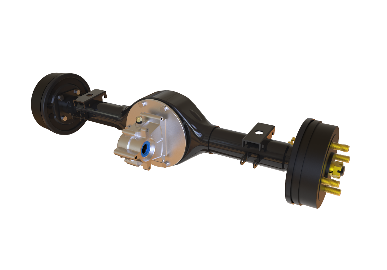
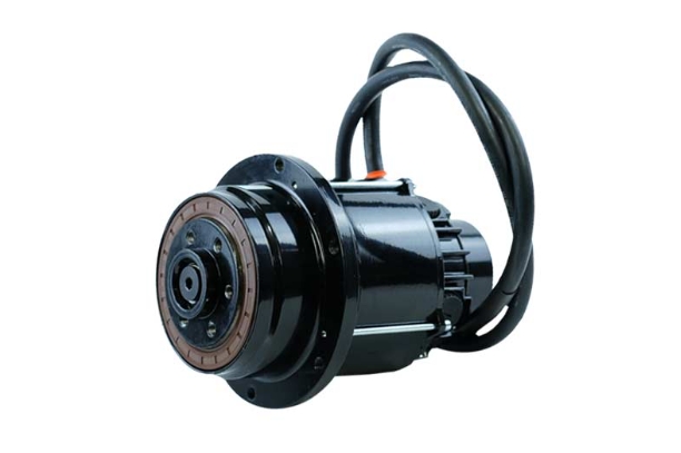
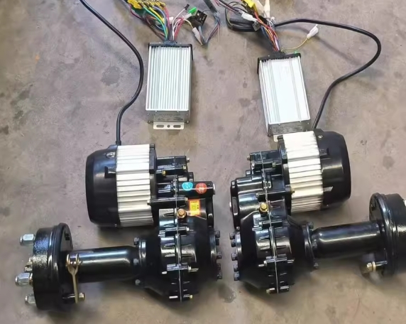
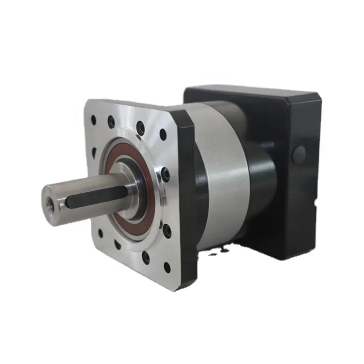
This in-wheel motor is designed to fit inside a 14-inch wheel. Figure 1 shows the appearance of the developed in-wheel motor. The in-wheel motor consists of a motor part, a reducer part and a wheel hub part. In order to reduce the size of the entire assembly, the hanging mounting section is incorporated into the housing.
Assuming that most of the time, commuters do not drive on highways, but on city streets, where the top speed is set at the legal maximum speed limit of 60 km/h on ordinary roads. Figure 2 shows the measured results of the efficiency of the developed in-wheel motor. Based on the urban upper limit of 60km/h, the goal is to have the highest efficiency in the frequently used low to medium speed range (2040km/h), as shown in Figure 2.
Table 1 Design information of hub drive system


Figure 1 Schematic diagram of the wheel hub drive system

Figure 2 Schematic diagram of the efficiency of the hub drive motor
3. vehicle test
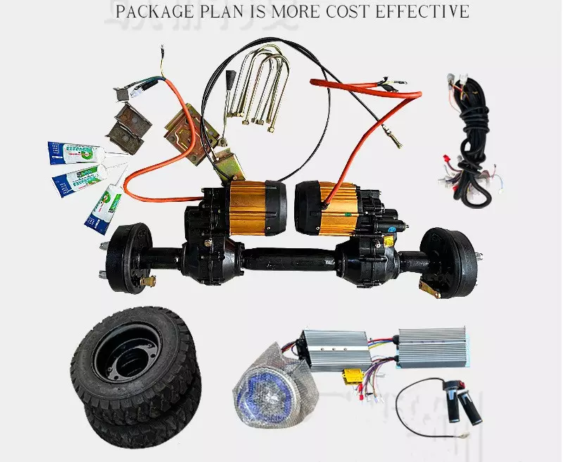
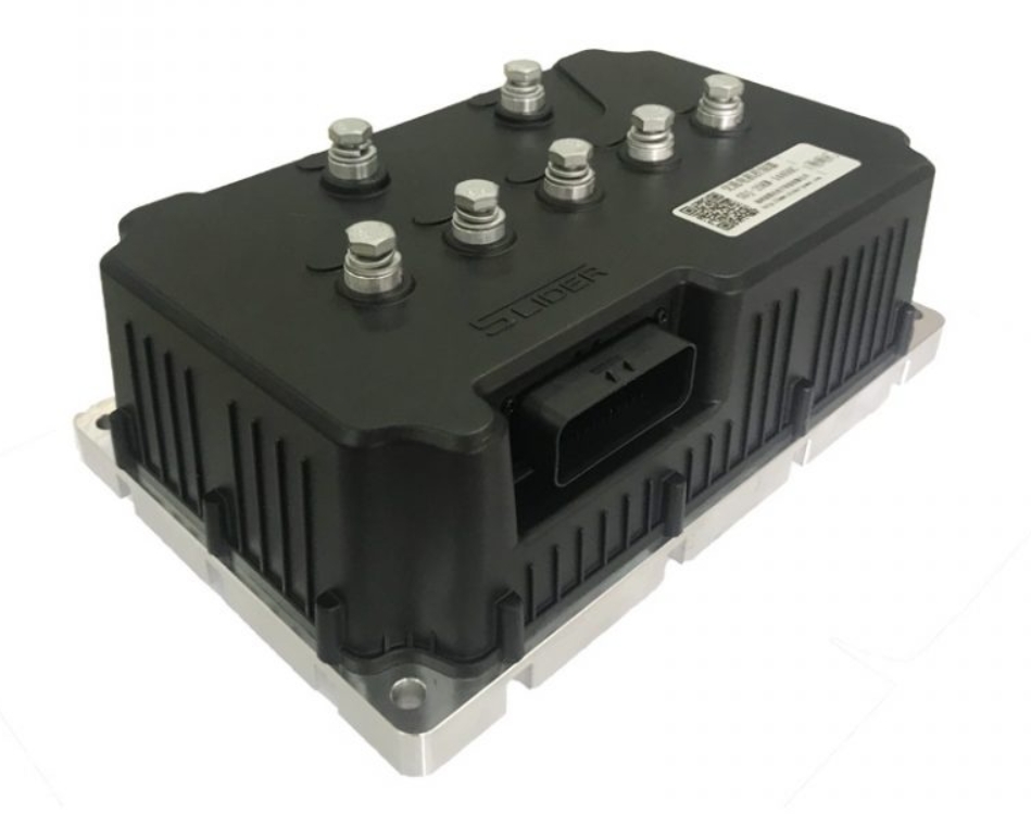
The in-wheel drive system was placed in the test vehicle. As shown in Table 2, the information of the test vehicle. As shown in Figure 3, the configuration diagram of the test vehicle, as shown in Figure 4, the appearance of the wheel hub drive system installed on the test vehicle. The vehicle control unit (VCU) determines the torque required to drive the electric motor based on the travel information from the accelerator operated by the driver, and sends a torque command to the inverter. In turn, the inverter converts the DC power from the power battery into the AC power required to drive the left/right motors, so that the left/right drive motors generate appropriate driving power according to the driving conditions.
Driving tests were carried out under the driving conditions in front, cornering conditions and cornering conditions, and it was verified that the test vehicle achieved smooth, strong acceleration characteristics and satisfactory stable driving control of new energy electric vehicles.
A photo of the space behind the seat of the test vehicle is shown in Figure 5. A usable space where both left/right suspensions can individually support their in-wheel drive systems. When the ability to carry luggage is very necessary, this space can be used as a luggage compartment. In this test car, the power battery was installed under the seat in the center of the test vehicle. When the test vehicle's focus is on its vehicle's cruising range, the above-mentioned available space can be used to carry its additional power battery. An optimized test frame and suspension system will allow for more efficient use of interior space.
Table 2 Design Information of Test Vehicles


Figure 3 Logic diagram of wheel hub drive system layout

Figure 4 Schematic diagram of test vehicle layout

Figure 5 Schematic diagram of the space behind the seat of the test vehicle
4. in conclusion
Considering that two-seater commuter vehicles will become a development trend of new energy electric vehicles; it has advantages in creating cabin space. Running tests on test vehicles equipped with its newly developed in-wheel drive system have confirmed the smooth and powerful acceleration performance of the new energy electric vehicle, as well as the satisfactory driving control stability; will continue to work on improving its differential Evaluate performance and reliability, and contribute to the popularization of two-seater new energy electric vehicles for commuting.
 XINDA
XINDA