


Six Elements of Motor Control
Rising consumer demands for power, reliability, functionality, and performance are driving rapid growth in electronic devices, including lawnmowers, refrigerators, vacuum cleaners, automobiles, and more. Manufacturers want full-scale delivery. Motor control plays a major role in delivering on these promises, and understanding the fundamentals is the first step in making that happen.
There are several motor control topologies available today: brushed, brushless DC (BLDC), stepper, and inductive. BLDC and permanent magnet synchronous motor (PMSM) are the two most closely related types of brushless motors.
Brushless motors eliminate the need for motor brushes and are used in many applications today. These BLDC topologies use commutation logic to move the rotor, increasing the efficiency and reliability of the motor. Let's go into details.
BLDC and PMSM motors work on the same principle as synchronous motors. The rotor continues to follow the stator with each commutation, so the motor can continue to run. However, the stator windings of the two DC motors have different geometries, which can result in different back electromotive force (BEMF) responses. BLDC BEFM is trapezoidal. The BEMF of a PMSM motor is sinusoidal, so the coil windings are wound sinusoidally. To maximize performance, these electrodes are typically sinusoidally commutated.
BLDC and PMSM motors ( Figure 1 ) generate electromotive force through their windings during operation. In any electrical machine, due to motion, the resulting EMF is called back electromotive force (BEMF) because the electromotive force induced in the electrical machine is the opposite of the electromotive force of the generator.

Figure 1 : BLDC and PMSM motors typically use sine wave commutation.
To achieve a sinusoidal waveform to control a PMSM motor, a Field Oriented Control (FOC) algorithm is required. FOC is often used to maximize the efficiency of PMSM three-phase motors. Compared with BLDC's ladder controller, PMSM's sinusoidal controller is more complex and more expensive. However, the increased cost also brings some advantages, such as reducing noise and harmonics in the current waveform. The main advantage of BLDC is easier control. In the end, it is best to choose a motor based on the application needs.
BLDC and PMSM motors are available with or without sensors. Motors with sensors ( Figure 2 ) are suitable for applications that need to start the motor under load conditions. These motors use Hall sensors, which are embedded in the electrode stator. Essentially, a sensor is a switch whose digital output is equivalent to the detected polarity of the magnetic field. A separate Hall sensor is required for each phase of the motor. Three-phase motors require three Hall sensors. Motors without sensors require an algorithm to operate using the motor as a sensor. They rely on BEMF information. By sampling the BEMF, the position of the rotor can be inferred, eliminating the need for hardware-based sensors. Regardless of the motor topology, controlling these motors requires knowledge of the rotor position so that the motor can commutate effectively.
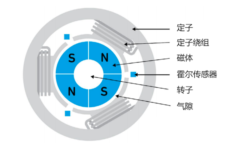
Figure 2: Schematic diagram of BLDC and PMSM motors.
Today, software algorithms such as computer programs (a set of instructions designed to perform a specific task) are beginning to be used to control BLDC and PMSM motors. These software algorithms improve motor efficiency and reduce operating costs by monitoring motor operation. Some of the key functions in the algorithm include motor initialization, Hall sensor position detection, and switch signal checking for raising or lowering the current reference.

A three-phase BLDC motor has 6 states. As shown in Figure 3 , the three-digit code can represent an opcode number between 1 and 6. The sensor is used to provide a three-bit data output via 6 of the 8 opcodes (1 to 6). This information is useful because the controller can determine when an illegal opcode has been issued and take action based on the legal opcodes (1 through 6). The algorithm takes the Hall sensor opcode and decodes it. When the Hall sensor opcode value changes, the controller changes the power delivery scheme to achieve commutation. The microcontroller uses the opcode to extract the power delivery information from the lookup table. After powering the three-phase inverter with the new sector command, the magnetic field shifts to the new position while pushing the rotor in the direction of movement. This process is repeated continuously while the motor is running.
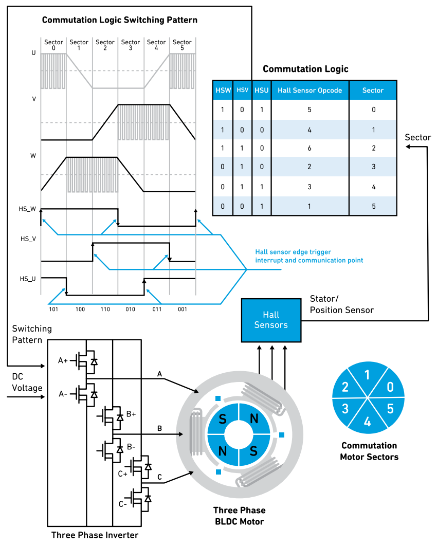
Figure 3 : Three-digit codes can be used to represent opcode numbers between 1 and 6.
 XINDA
XINDA