


How to install the coupling - how to find the alignment of the coupling
The alignment of the coupling is also called the alignment. After the pump and the motor are installed, the last task is to find the concentricity between the pump and the motor, that is, to make the axis of the pump and the prime mover on the same straight line so that it does not cause vibration during operation. When the newly installed pump is aligned, the radial and axial errors of the coupling may appear in the following four situations:

method one
General pumps (water pumps, small oil pumps) can be roughly measured with a flat ruler or feeler gauge, but most equipment requires precise measurement and a dial indicator is used for measurement. Generally, the levelness of the pump has been found. Based on the counter-wheel of the pump, measure and adjust the counter-wheel of the motor to ensure the alignment of the two shafts of the motor and the pump.
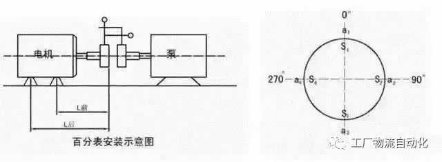
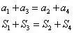
Note: a1, a2, a3, a4 represent the radial clearance, S1, S2, S3, S4 represent the axial clearance. When measuring the axial clearance, first measure the radial clearance a1 and the axial clearance S1 when the dial indicator is at 0o, and then measure them respectively. Find the radial and axial clearances of 90o, 180o, and 270o, and record them respectively inside and outside the circle shown in the figure above. When the measurement returns to 0o, it must be consistent with the original reading, otherwise, the cause must be found, which is generally caused by shaft movement or ground bolt looseness. The final measurement data must also meet the following conditions to indicate that the calculation is correct.

Method Two
Mount the dial indicator to the pump end, align the dial indicator to zero, rotate the counter wheel once, and get a value every 90 degrees. Finally, when the dial indicator turns back to its original position, it must return to zero. The sum of the left and right readings should be equal to The sum of the upper and lower values. Then analyze the relative spatial position of the two axes according to the readings, and make appropriate adjustments according to the deviation value. First adjust the left and right deviation of the coupling to the allowable value, and then adjust the height to within the standard.
Correction formula:
-
S1= ±(Axial difference of the opposite wheel (absolute value of mouth opening)×distance from 1 to the measuring point)÷Measuring point diameter±circumferential radial interpolation (difference) value/2;
-
S2= ±(Axial difference of opposite wheel × distance from foot 2 to measuring point) ÷ measuring point diameter±circumferential radial interpolation (difference) value/2.
The first ±: If the opposite wheel is the upper opening, take the "+" sign; if it is the lower opening, take the "-" sign, which can be understood as from top to bottom;
The second ±: take "+" when the motor is low; take "-" when the motor is high.
If S1 is positive (the opening is open and the motor is low), it means that gaskets should be placed, and the number of S1 is the thickness of gaskets to be placed.
Another: The diameter of the measuring point is the rotating diameter of the measuring point, not the diameter of the coupling. Adjusting left and right is similar.

method three
Addition and subtraction mat calculation method
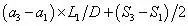
in:
-
a indicates the axial meter reading
-
D is the diameter of the backrest wheel
-
L1 indicates the distance from the backrest wheel to the front foot of the motor
-
L2 indicates the distance from the front foot of the motor to the rear foot
-
S means the reading of the radial meter
The result of this is the amount of pad your motor will add to the front and rear feet.

Alignment of the double watch is good, but the axial p displacement is sometimes difficult to grasp. Novices may not be able to do it for a long time by luck, but masters can do it in ten minutes with experience!
It is best to add an axial table at 180°. The so-called three-table alignment!
 XINDA
XINDA