


Comparison of the transmission principle diagram of the reducer
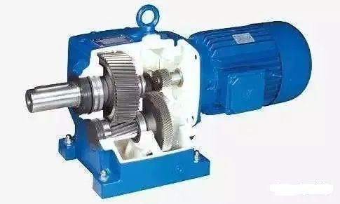
The reducer is generally used for transmission equipment with low speed and high torque. The motor, internal combustion engine or other high-speed running power is used to achieve the purpose of deceleration through the gear with a small number of teeth on the input shaft of the reducer meshing with the large gear on the output shaft. The ratio of the gear teeth is the transmission ratio.
The reducer is a relatively precise machine, the purpose of using it is to reduce the speed and increase the torque. There are many types of reducers with different models, and different types have different purposes.
According to the transmission type, it can be divided into gear reducer, worm reducer and planetary gear reducer; according to the number of transmission stages, it can be divided into single-stage and multi-stage reducer; according to the gear shape, it can be divided into cylindrical gear reducer and bevel gear reducer And conical-cylindrical gear reducer; according to the layout of the transmission, it can be divided into expansion type, shunt type and coaxial type reducer.
In order to facilitate the reasonable selection of reducers, the types, characteristics and applications of several common reducers are listed one by one for reference when selecting models.
1. Single-stage cylindrical gear reducer
Single-stage cylindrical gear reducer is suitable for reduction ratio 3~5. The gear teeth can be straight teeth, helical teeth or herringbone teeth, and the box body is usually made of cast iron or welded with steel plates. Rolling bearings are commonly used for bearings, and sliding bearings are only used for heavy loads or extremely high speeds.
2. Two-stage cylindrical gear reducer
Two-stage cylindrical gear reducer is divided into three types: expansion type, shunt type and coaxial type, and the applicable reduction ratio is 8~40.
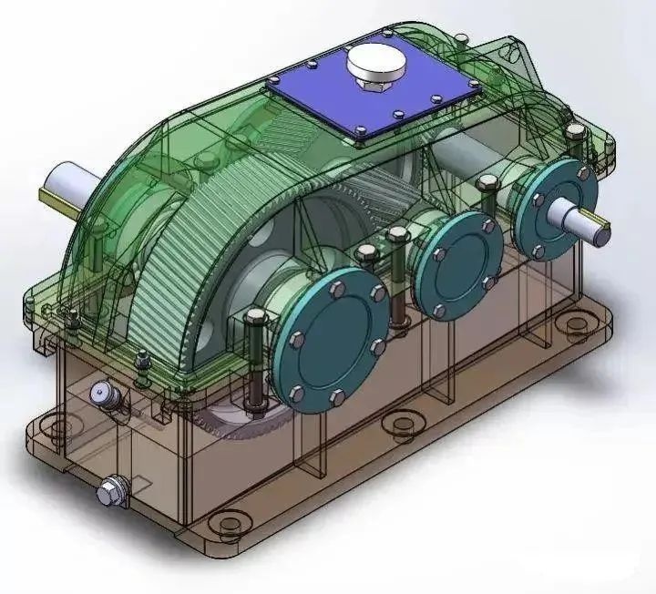
Expansion type: high-speed long-tail helical gear, low-speed gear can be straight or helical. Due to the asymmetrical arrangement of the gear relative to the bearing, the rigidity of the shaft is required to be large, and the torque input and output ends are kept away from the gear to reduce the uneven distribution of load along the tooth width caused by the bending deformation of the shaft. The structure is simple and the application is the widest.
Shunt type: Generally, high-speed grade shunt is used. Since the gear is arranged symmetrically with respect to the bearing, the force on the gear and the bearing is relatively uniform. In order to make the total axial force on the shaft smaller, the helical directions of the two pairs of gears should be opposite. The structure is more complicated, and it is often used in places with high power and variable loads.
Coaxial type: The axial size of the reducer is large, the intermediate shaft is long, and the rigidity is poor. When the oil immersion depth of the two large gears is similar, the load-carrying capacity of the high-speed gear cannot be fully utilized. It is often used in places where the input and output shafts are coaxial.
3. Single-stage bevel gear reducer
Single-stage bevel gear reducer is suitable for reduction ratio 2~4. The transmission ratio should not be too large to reduce the size of the bevel gear and facilitate processing. It is only used in the transmission where the two axes are perpendicular to each other.
4. Conical and cylindrical gear reducer
Conical and cylindrical gear reducers are suitable for reduction ratios of 8~15. The bevel gear should be arranged in the high-speed stage to reduce the size of the bevel gear. Bevel gears can be straight or curved. Cylindrical gears are mostly helical teeth, so that they can offset part of the axial force with bevel gears.
5. Worm reducer
There are mainly cylindrical worm reducers, arc toroidal worm reducers, bevel worm reducers and worm-gear reducers, among which cylindrical worm reducers are the most commonly used.
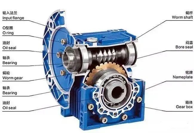
The worm reducer is suitable for the reduction ratio of 10~80. The structure is compact, the transmission ratio is large, but the transmission efficiency is low, and it is suitable for occasions with small power and gap work. When the peripheral speed of the worm is V≤4~5m/s, the worm is a bottom type, and the lubrication and cooling conditions are better; when V≥4~5m/s, the agitation loss of the oil is relatively large, and the general worm is an upper type.
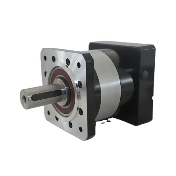
6. Planetary gear reducer
Due to the structure of the planetary reducer, the minimum single-stage reduction is 3, and the maximum generally does not exceed 10. The common reduction ratio is: 3/4/5/6/8/10. The number of stages of the reducer generally does not exceed 3, but some are large The reduction ratio customized reducer has 4 stages of reduction.
Compared with other reducers, the planetary reducer has high rigidity, high precision (within 1 point for a single stage), high transmission efficiency (97%-98% for a single stage), high torque, volume ratio, and maintenance-free for life, etc. features. Because of these characteristics, most planetary reducers are installed on stepper motors and servo motors to reduce speed, increase torque, and match inertia.
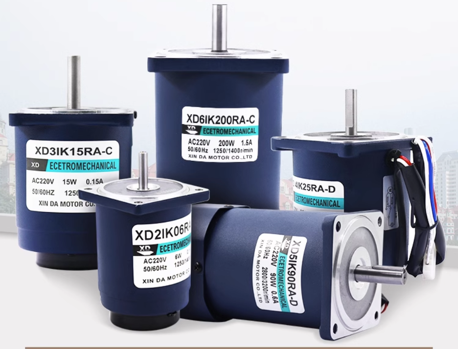
 XINDA
XINDA