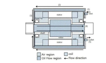
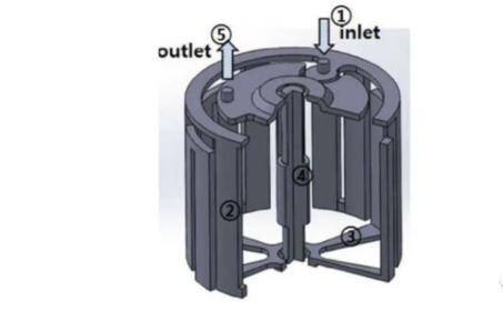
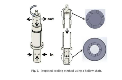
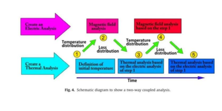
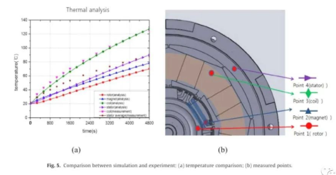
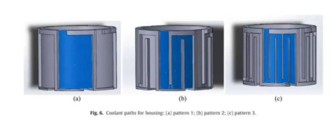
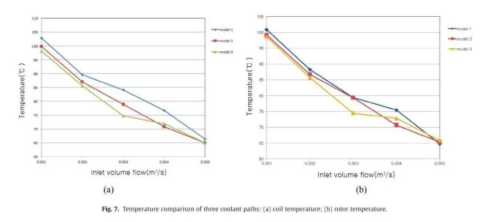
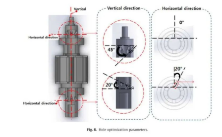
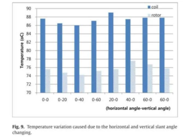
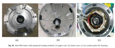
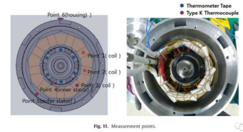
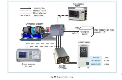
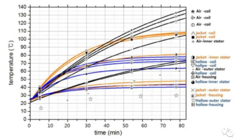
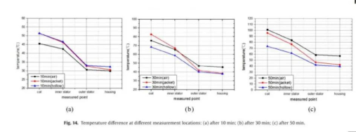
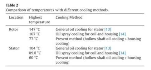
Today, I will bring you an interpretation of the electric vehicle rotor oil-cooled motor scheme. It introduces the optimization process of each variable in the oil circuit design in detail and makes a comparative analysis of each scheme. This article interprets its design process, hoping to help you solve practical problems. 1. Oil road direction First of all, let's take a look at the overall scheme of the motor oil cooling we are going to discuss. The direction of the oil circuit is shown in the figure below: Compared with the traditional scheme, this scheme is special in that, on the basis of the general stator water cooling scheme, the cooling oil circuit of the rotor is added. The cooling oil flows into the casing from the front cover, forms an annular oil passage in the stator core, collects from the back cover to the inside of the rotor, and reaches the outlet of the front cover from the inside of the rotor. 2. Motor oil cooling structure In order to realize the above oil circuit, the structure of the front and rear covers and casing of the motor is shown in the figure below: It is worth mentioning that the axial oil passage of the motor casing adopts multiple inlets and outlets, so that the flow resistance of the oil passage is relatively small. In addition, for the rotor, it is processed in two stages and then welded. The structure is as follows: 3. Simulation iterative process The basic process of simulation is shown in the figure below: The simulation process is based on the two-way coupling analysis of the temperature field and the electromagnetic field. First, the initial temperature is given, and then the loss at this temperature is calculated through electromagnetic simulation, and then the loss is passed to the temperature field analysis. Repeat this iteratively until the steady state. In order to shorten the simulation time, the electromagnetic field simulation adopts 2D digital model, the temperature field simulation adopts 3D digital model, and the heat transfer coefficient of the relative air gap between the rotor and the stator refers to the empirical value. Fourth, the actual measurement verification The different positions and actual temperature values of the motor were measured, and a comparative analysis was carried out with the simulated values. Taking the working condition of 2300rpm and 7.38Nm as an example, the simulation error can be obtained within 10%. See the figure below for specific values: Five, the optimization of the motor 1. Case cooling oil channel The oil passages in three different forms are as follows: Analyze the stator and rotor temperatures of the three structures under different flow conditions as shown in the figure below: It can be seen from the chart that we can determine the structure of the casing oil passage after comprehensive consideration according to the system flow and temperature requirements. It is obvious that from a to b, when the cooling oil flow rate is low, the cooling effect of the winding has been significantly improved, while the cooling effect of c is not significantly improved compared with b; when the cooling oil flow rate is high, the cooling effect of c Neither the winding nor the rotor is as good as b, even if its structure is more complicated. This shows that when we design the oil channel of the casing, we need to design it in combination with the flow of cooling oil, so as to find an optimal cooling solution that matches the flow and channel design. 2. Rotor inlet and outlet The angle of the oil inlet and outlet of the rotor is an optional variable, and its variable can be set as the angle shown in the figure below. By simulating several sets of specific angle values, the results shown in the figure below can be obtained. The comparison shows that the third group combination is the optimal solution. 6. Test methodIn the actual prototype, six oil cooling passages are opened on the stator casing. As shown below: To measure the temperature of the stator and rotor, place thermistors on the stator wire package, iron core, and casing respectively. The rotor cannot be directly measured, and the label paper is used to measure it. The measurement points are as follows: Test system: 7. Test results Three conditions: air cooling, single casing oil cooling and casing plus shaft oil cooling result: After 80 minutes of air cooling, the temperature of the motor is 130°C, and the balance has not been reachedAfter 80 minutes of single-case oil cooling, the temperature of the motor reaches 110°C, reaching equilibriumAfter 30 minutes, the motor temperature reaches 80°C when the housing is cooled with shaft oil, reaching equilibrium In addition, from the comparison of the time axis, the cooling effect of the single casing oil cooling and the casing plus shaft oil cooling is roughly the same before 10 minutes. After 30 minutes, the cooling effect of the two is obviously different, and the trend of this difference is expanding. . This scheme is compared with the cooling effect of the common single shell cooling and oil injection scheme, as shown in the following table: 8. Summary Compared with the traditional air-cooled solution, the coil temperature drops by 50%, and compared with the single-case oil-cooled solution, the coil temperature drops by 38%, so it is an effective solution to improve the cooling capacity of the motor.


 XINDA
XINDA