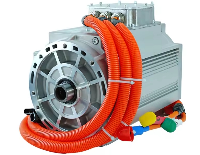
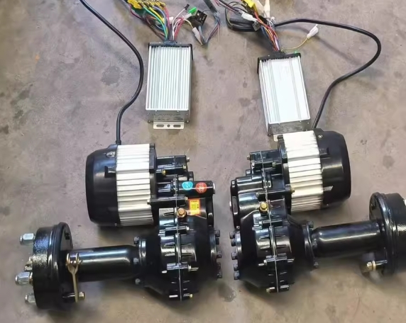
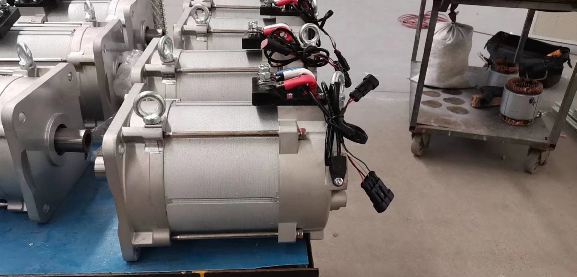
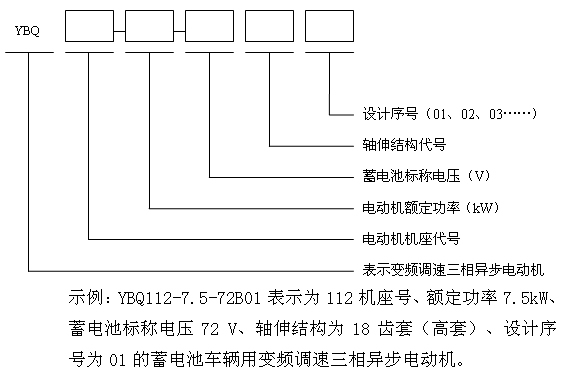
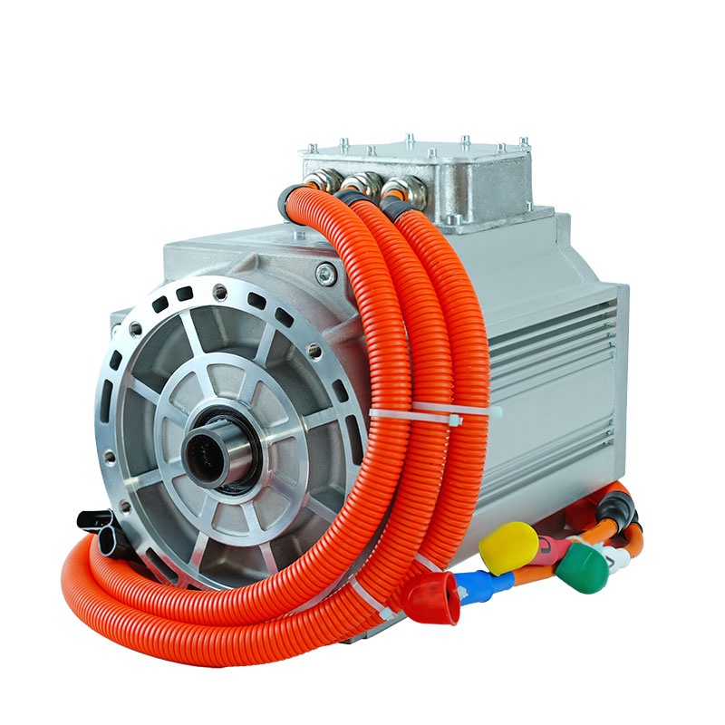
YBQ series three-phase AC variable frequency traction motor is suitable for various electric vehicles (electric cars, forklifts, trucks, tour buses, patrol cars, tractors, golf carts, etc.) powered by batteries and matched with controllers and electric vehicles. drive motor.
1. Product overview:
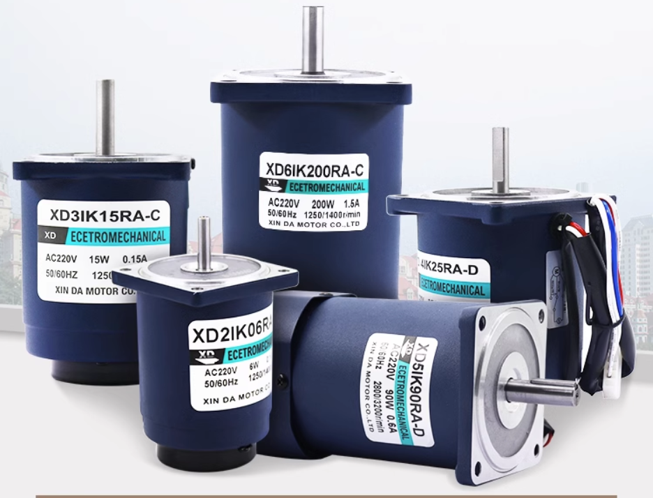
1.1 Product name: Three-phase AC variable frequency motor
Product standard: Q/0303ZXP003-2013 "Variable frequency variable speed three-phase asynchronous motor for battery vehicles"
1.2 Specifications and models are as follows:
1.3 See Table 1 for the structural codes of the machine base and shaft extension.
|
Base code
|
Shaft extension structure code
|
|
80, 90,
100 112, 132, 160
180, 200, 225
250, 280 , 315
|
A: 19-tooth sleeve B: 18-tooth sleeve (high sleeve) D: Smooth shaft flat key
E: 18-tooth spline shaft F: 18-tooth sleeve (low sleeve) H: 22-tooth shaft I: 10
-tooth sleeve L: 22-tooth Set M: Six-tooth spline shaft
Q: Flat head shaft V: 24-tooth set (high set) Z: Taper shaft
|
1.4 Environmental conditions of use:
The motor can operate normally under the following environmental conditions.
a. The altitude does not exceed 1000m;
b. The maximum temperature of the surrounding air is 40℃ and the minimum temperature is -25℃;
c. The relative humidity reaches 100%, and condensation forms on the surface of the motor.
1.5 can meet various working conditions such as heavy-load starting, full-load climbing and high-speed operation on flat roads.
1.6 For the installation appearance and technical parameters of the motor, refer to the product outline drawing and order requirements.
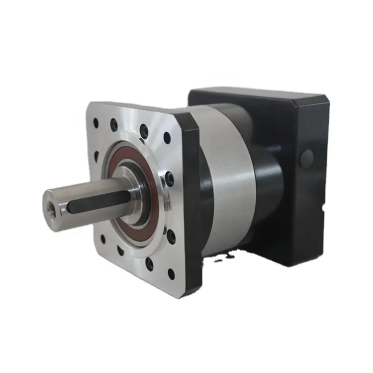
2. Motor structure and working principle:
2.1 The motor is mainly composed of stator, rotor, end cover and other components.
2.2 The motor shell protection level is IP54 (see GB/T4942.1).
2.3 The cooling method of the motor is IC410 or IC411 (see GB/T1993).
2.4 The working system of the motor is S2-60min short-time working system.
2.5 The insulation class of the motor is H class.
2.6 Motor wiring:
The inside of the motor stator winding is connected to "△" or "Y" according to the requirements of the corresponding product drawing, and three leads are drawn out, marked U (yellow), V (green), and W (red) respectively. When the outlet terminal is marked with letters When the sequence is the same as that of the three-phase power supply voltage of the controller, the motor rotates clockwise when viewed from the shaft extension end (can also be customized according to customer requirements).
2.7 The motor uses an external encoder, and the number of pulses is according to the corresponding drawing requirements. The encoder leads to four connections. The encoder connector code is DJ7041-1.5-11 (it can also be configured according to customer requirements).
2.8 Motor temperature sensor
KTY84-130. The temperature sensor (can also be configured according to customer requirements) corresponds to different resistance values at different temperatures. The resistance signal is transmitted to the controller, and then the controller performs reasonable control to protect the motor. The sensor uses DJ7021-1.5-11 connector (can also be configured according to customer requirements)
3 Notes
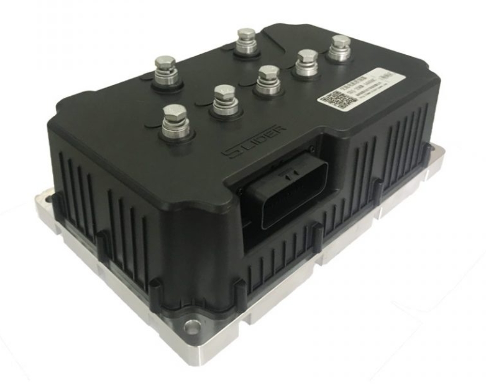
3.1 This motor is matched with an AC variable frequency controller. The motor and controller are closely configured and need to be adjusted and set before they can be combined. .
3.2 Users must comply with the requirements of this manual so that the manufacturer can ensure the normal operation of the motor.
3.3 Before use, use a 500-volt megger to measure the insulation resistance of the motor in the cold state. The value should be greater than 100MΩ, and the insulation resistance in the hot state (130°C) should not be less than 0.33MΩ.
3.4 The motor must be stored in a dry, clean, and ventilated place before use. If it is stored for too long (half a year), check whether the bearing grease has dried up. The insulation resistance value should be no less than 20MΩ, otherwise the motor should be placed in a drying oven for 0.5-1 hour, and the baking temperature should be 80-100°C, not too high.
3.5 Before use, check whether the motor wiring and speed sensor wiring are correct, firm and reliable.
3.6 Gently turn the shaft extension by hand to check whether the rotor rotates flexibly.
3.7 When the ambient cooling air temperature is not higher than 40°C, the temperature rise limit of the motor's stator winding (resistance method) is 105K, and the rolling bearing temperature does not exceed 95°C.
3.8 The working system of the motor is generally S2-60min short-time working system. It is not allowed to work continuously for a long time. If overtime work is required, it should be specially stated when ordering.
3.9 Every six months when the motor is in operation, it should be inspected and maintained as follows:
a. Clean the sediment and other foreign objects on the casing regularly to avoid affecting the heat dissipation of the motor.
b Check whether the bearing rotates flexibly, clean or replace the bearing, and fill the raceway with 7015 grease (SH/T037017-1993) after cleaning.
c Planned maintenance at least once a year.
3.10 Motor accessories can be added to the order contract according to customer requirements and will be priced separately.
3.11 The motor comes with a certificate and usage and maintenance instructions.
3.12 Warranty period: The complete motor is guaranteed for one year from the date it leaves the factory. Users should strictly abide by the requirements of this maintenance manual. Motor failures caused by improper use by users are not covered by the warranty. During the warranty period, if the motor is abnormal, the user should promptly Contact the manufacturer and do not handle it yourself.
Appendix: Common motor faults and solutions
|
Fault phenomenon
|
Cause Analysis
|
Approach
|
|
Motor
cannot start
|
1. The power supply phase is missing or the power supply voltage is too low.
2. If the rotor is broken or desoldered, the motor can be started without load, but cannot be started with load.
3. The motor load is too large or the transmission mechanism is stuck.
|
1. Check whether there is any broken wire in the stator winding, and then check the power supply voltage.
2. Use the rotor broken bar tester to check whether the rotor has any defects such as broken bars or cracks.
3. Select a larger capacity motor to eliminate mechanical transmission mechanism failures.
|
|
Motor
three-phase current unbalanced
|
1. The three-phase power supply voltage is unbalanced.
2. Some coils in the stator winding are short-circuited.
|
1. Use a voltmeter to measure the power supply voltage.
2. Use an ammeter to measure the three-phase current or disassemble the motor and check the overheating coil by hand.
|
|
Motor
bearing overheating
|
1. The bearing is damaged.
2. The bearing and shaft or end cover are too tight or too loose.
3. There is too much, too little or too dirty grease, and there are sand, dust and foreign matter.
4. The motor installation is not concentric.
|
1. Replace the bearings.
2. Repair the shaft or end cover to match the bearing.
3. Clean the bearing and fill 2/3 of the space with clean grease.
4. Adjust the coaxial condition of the motor installation.
|
|
Fault phenomenon
|
Cause Analysis
|
Approach
|
|
The motor temperature rises too high or smokes
|
1. The motor is overloaded.
2. The power supply voltage is too high or too low.
3. The stator and rotor collide with each other.
4. The motor is poorly ventilated.
5. The stator winding has a short circuit or ground fault.
6. Poor welding or desoldering.
7. Single-phase operation.
8. The ambient temperature is too high.
|
1. Reduce the load or replace the motor with a larger capacity.
2. Adjust the power supply voltage.
3. Check whether the rotor core is deformed, whether the shaft is bent, whether the end cover is too loose, and whether the bearings are worn.
4. Check whether the air path is blocked.
5. Use a bridge to measure the DC resistance of each phase winding, use a megohmmeter to measure the insulation resistance of the winding to the chassis, and replace and repair the coil.
6. Check the solder joints.
7. Check the power supply and windings to eliminate single-phase operation faults.
8. Take cooling measures.
|
|
The motor vibrates loudly and makes abnormal noise during operation.
|
1. The motor installation does not meet the requirements.
2. The bearing is poorly assembled or damaged.
3. The rotor is dynamically unbalanced.
4. The motor runs out of phase and makes a buzzing sound.
5. The bearing is seriously short of oil.
|
1. Check the motor installation and make adjustments.
2. Check the bearing assembly or replace the bearing.
3. Perform rotor dynamic balance correction.
4. Troubleshoot the motor phase failure.
5. Clean the bearings and fill 2/3 of the space with clean grease.
|


 XINDA
XINDA