


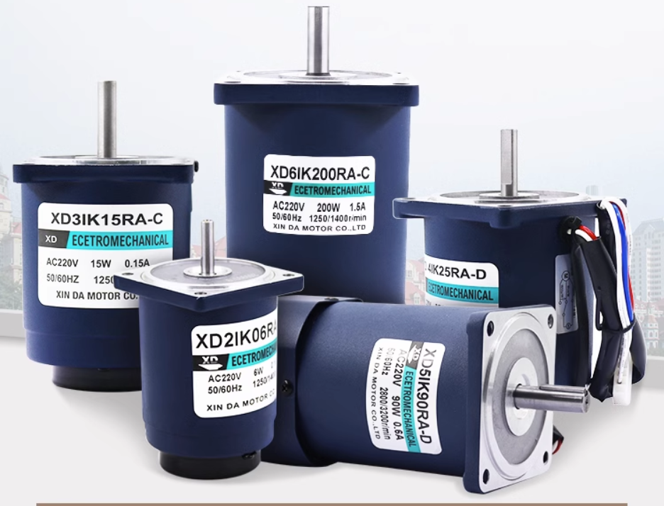


How to control a brushless motor and how to perform basic maintenance?
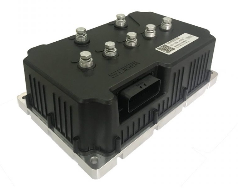
Brushless motors have three control methods: square wave control, sine wave control, and FOC control. The controller sometimes causes the motor to be unloaded or the current and voltage are adjusted. This requires maintenance according to the specific situation. Xinda Motor will introduce it in detail below.
1. Control method of brushless motor
1. Square wave control
Square wave control uses a Hall sensor or a non-inductive estimation algorithm to obtain the position of the motor rotor, and then commutates 6 times (once every 60°) according to the position of the rotor within a 360° electrical cycle. The motor outputs a force in a specific direction at each commutation position, so it can be said that the position accuracy of square wave control is electrical 60°. Because under this control method, the phase current waveform of the motor is close to a square wave, it is called square wave control. The advantage is that the control algorithm is simple, the hardware cost is low, and a higher motor speed can be obtained by using a controller with ordinary performance; the disadvantage is that the torque fluctuation is large, there is a certain amount of current noise, and the efficiency cannot reach the maximum value. Square wave control is suitable for situations where the rotation performance of the motor is not high.
2. Sine wave control
The sine wave control method uses SVPWM wave, which outputs a 3-phase sine wave voltage, and the corresponding current is also a sine wave current. This method does not have the concept of square wave control commutation, or it is considered that an infinite number of commutations are performed within an electrical cycle. Obviously, compared with square wave control, sine wave control has smaller torque fluctuations and fewer current harmonics, and the control feels more "delicate". However, the performance requirements of the controller are slightly higher than those of square wave control, and the motor efficiency cannot be reached. maximum value.
3. FOC control
Sine wave control realizes the control of voltage vector and indirectly realizes the control of current magnitude, but it cannot control the direction of current. The FOC control method can be considered as an upgraded version of sine wave control, which realizes the control of the current vector, that is, the vector control of the motor stator magnetic field.
2. Basic maintenance of brushless motor controller
1. The motor is no-loaded, and some motors are around 1.8A. When the control panel does not work, first check the signal light on the board flashing in seconds/times. If the turn signal is not added but the signal light does not flash, you should check:
Is the 5V voltage normal? If not, is there a short circuit in the external connector? Is there a tin short circuit on the board?
Is the voltage at pin 2 of the microcontroller 5V?
Does the quartz crystal work;
Is the signal light damaged?
2. Controller current and voltage adjustment
Current adjustment: adjust the length of constantan (the new program can adjust the resistance (R6) of LM358 pin 6 to ground, the value range is from 2K to 3.3K, adjust to the required operating current, (the old program for 500W has 26A to 35A Better operating results, the new program has better results from 22A to 28A.)
Voltage adjustment: The undervoltage sampling circuit is composed of two voltage dividing resistors from the 48V or 36V power supply to the ground. Usually, the undervoltage point can be adjusted by adjusting the resistance (Ra) connected to the power supply. Because the resistance connected to the ground is usually 1.2K, so The undervoltage value and resistor value can be calculated according to the following formula: Ra=(1.2xv-1.2x3)/3 Example: Using 48V battery voltage, when the undervoltage V value is 40.5: Ra=(1.2x40.5-1.2 x3)/3-------→Ra=15K Note: 1.2 is the resistance connected to ground. 3 in the formula is the undervoltage AD value processed by the microcontroller. When the undervoltage value needs to be adjusted between 40.5V and 42V, when the 1.2K resistor is fully loaded and 82K, 39K, 36K, 33K, and 30K are connected, the undervoltage corresponds to: 41.04V, 41.65V, 41.75V, 41.86V, and 42V respectively.
 XINDA
XINDA