
















How to determine the skewness of a motor slot?
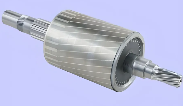
In motor skew design, selecting the right stator or rotor skew slot is only the foundation; the skew angle is the key factor determining motor noise, torque, efficiency, and temperature rise. If the skew is too small, it cannot cancel tooth harmonics, resulting in poor noise reduction and texture suppression; if the skew is too large, it will weaken the fundamental magnetic field, reduce back EMF, lose output torque, and cause additional axial losses.
The optimal principle for skew slot selection is to maximize the cancellation of first-order tooth harmonics while minimizing the sacrifice of fundamental torque and operating efficiency. The industry's optimal design approach is to match the axial skew slot offset of the iron core with the pole pitch of the first-order tooth harmonics, so that the synthesized harmonics of each micro-segment of the slot conductor cancel each other out, while maximizing the utilization rate of the fundamental magnetic field and eliminating performance loss caused by excessive skew slotting.
This set of formulas is applicable to the vast majority of motors and is a universal standard for simulation analysis and mass production design.
1. Mechanical skew angle (theoretically optimal). The mechanical skew angle = 360° / number of stator slots, corresponding to the industry's classic "single-slot skew" benchmark scheme. This offset ensures that the first-order tooth harmonics at any cross-section along the motor slot axis always have a phase difference of 180°, effectively canceling cogging torque, electromagnetic howling, and torque pulsation. It is the optimal theoretical value for harmonic suppression.
2. Electrical Angle Conversion. Electrical angle conversion is commonly used in electromagnetic design: Spur slot electrical angle = Mechanical spur slot angle × Number of pole pairs. The optimal range for engineering applications is 10°–15° electrical angle, representing a golden value range that balances harmonic suppression and torque preservation.
The theoretical values need to be fine-tuned based on the operating conditions, and the values of the skew slots differ significantly for motors with different pole numbers.
1. Multi-pole low-speed motors (8/10/12 poles and above): Select standard full-slot skew (1 slot pitch). Multi-pole motors have dense tooth slots, complex harmonics, and are sensitive to low-speed torque pulsation, making them highly dependent on skew. Full-slot skew can completely suppress high-order harmonics and eliminate low-speed jitter and noise. These motors have high torque redundancy, and the slight performance loss caused by skew is negligible.
2. Medium-pole general-purpose motors (4/6 poles): Select 0.8 to 1 slot pitch. As a mainstream industrial motor, 4/6 pole motors have moderate harmonic amplitude and do not require full skewed slot design. Small skewed slots can improve electromagnetic noise, low-speed creep, and torque fluctuations, while reducing fundamental wave loss, balancing efficiency and performance. They are suitable for high-volume production scenarios such as fans and water pumps, offering the best cost performance.
3. 2-pole high-speed motors: If necessary, select a small skewed slot of 0-0.5 times, with straight slots preferred. 2-pole high-speed motors have good magnetic field sinusoidality and low cogging torque, making skewed slot optimization yield minimal benefits. Under high-speed conditions, skewed slots amplify axial magnetic losses and iron losses, leading to a decrease in back EMF and excessive temperature rise. Straight slots are preferred in design; only minor noise issues may warrant a very small skewed slot, and full skewed slot designs are strictly prohibited.
For motors with the same slot and number of poles, the values used differ. Asynchronous motors use skewed rotor slots, allowing for the direct use of 1 standard slot pitch without additional eddy current losses. This also solves the start-up creep problem and provides high design tolerance. Permanent magnet motors use skewed stator slots, and it is recommended to use smaller values. Excessively large skew slots will reduce torque density and weak magnetic properties, affecting accuracy during servo control.
First, blindly increasing the skewed slot for noise reduction is prohibited. Skewed slots have a performance threshold; exceeding the slot pitch by more than 1 times no longer improves harmonic suppression, but torque loss and temperature rise will continue to worsen. Second, high-precision servo motors should not have fully skewed slots. A combination of small-amplitude skewed slots, magnet segmentation, and slot opening optimization is required to ensure torque linearity and control accuracy. Third, the upper limit of skewed slots for high-speed motors must be strictly controlled to avoid differential frequency noise and high-speed overheating. Fourth, the skewed slot angle must match the number of slots per pole and per phase, and be adapted to high and low order harmonic characteristics as needed.
 XINDA
XINDA