B L O G
XINDA MOTOR
  1. Home
  2. Knowhow

A full explanation: motor rotation principle, structure, type, troubleshooting

Date:2023-02-21   Author:XINDA MOTOR
Motors are ubiquitous in the field of equipment. Motor type, soft start method, selection steps, damage causes and treatment methods, what is the difference between good and bad motors... Let's take a look together in this issue.


Principle of motor rotation


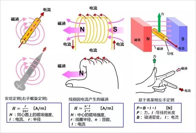
1. Electric current, magnetic field and force


First, for the convenience of the subsequent explanation of the principle of electric machines, let's review the basic laws/laws concerning electric current, magnetic field and force. Although there is a sense of nostalgia, it is easy to forget this knowledge if you do not use magnetic components regularly.


2. Detailed explanation of rotation principle  


The following describes the rotation principle of the motor. We combine pictures and formulas to illustrate.

When the leadframe is rectangular, take into account the forces acting on the current flow.


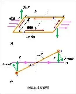
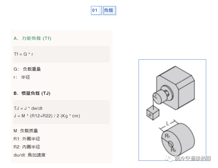
The force F acting on sides a and c is:


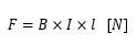
Generates torque about the central axis.

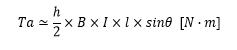
For example, when considering the state where the rotation angle is only θ, the force acting at right angles to b and d is sinθ, so the torque Ta of part a is expressed by the following formula:

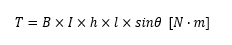
Considering part c in the same way, the torque is doubled and results in a torque calculated by:

Since the area of the rectangle is S=hl, substituting it into the above formula yields the following result:


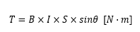
This formula works not only for rectangles, but also for other common shapes like circles. Electric motors take advantage of this principle.

Key Takeaways:

The principle of rotation of a motor follows laws (laws) related to current, magnetic field and force.
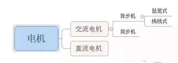
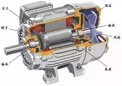
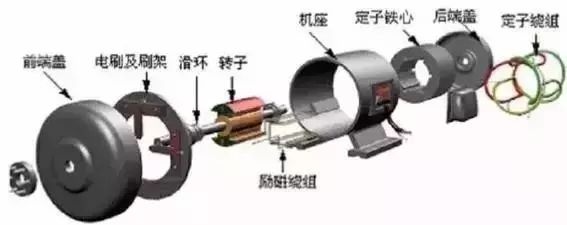
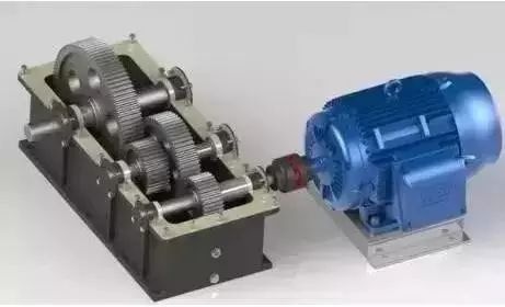
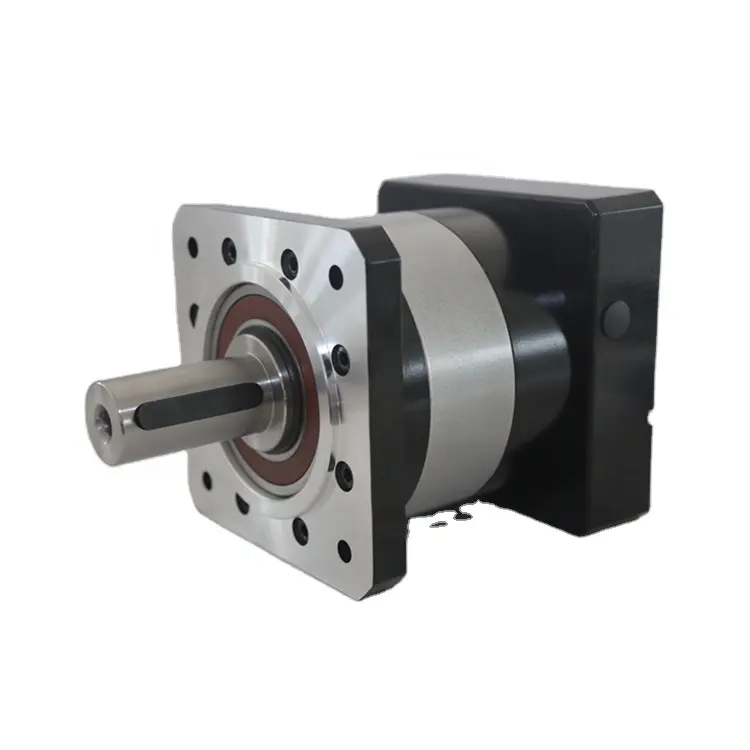
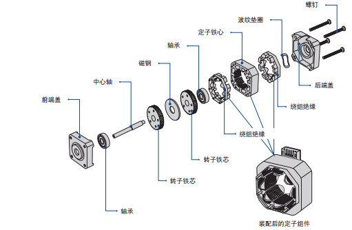
  
DC motors vs AC motors


1. The difference between DC and AC motors


Schematic diagram of DC motor structure


Schematic diagram of AC motor structure

(1) The power supply mode is different:
DC motor: use DC as power supply;
AC motors: use alternating current as a power source.

(2) Different in structure:
The principle of the DC motor is relatively simple, but the structure is complex and not easy to maintain. The principle of the AC motor is complicated but the structure is relatively simple, and it is easier to maintain than the DC motor.


DC motor
(3) Different prices:
The DC motor with the same power is higher than the AC motor, including the speed control device for controlling the speed, and the price of the DC speed control device is higher than that of the AC speed control device. Of course, the structure and maintenance are also very different.

(4) The performance is different:
Because the speed of the DC motor is stable and the speed control is precise, which cannot be achieved by the AC motor, so the DC motor has to be used instead of the AC motor under the strict requirements of the speed. AC motor speed regulation is relatively complicated, but it is widely used because chemical plants use AC power.


Synchronous Motors vs Asynchronous Motors
  
Synchronous and asynchronous refers to whether the rotor speed and the stator rotating magnetic field speed are synchronous (same) or asynchronous (lag), so only AC can generate a rotating magnetic field, and only AC motors have the concept of synchronous and asynchronous.


How stepper motors work

1. Synchronous motor   
Principle: rely on "the magnetic field always goes along the shortest direction of the magnetic circuit" to realize the one-to-one correspondence between the rotor magnetic poles and the stator rotating magnetic field poles, and the rotating speed of the rotor magnetic poles is the same as that of the rotating magnetic field.
Features: Whether the synchronous motor is used as a motor or a generator, its speed and AC frequency will be strictly unchanged. Synchronous motors have a constant speed and are not affected by load changes.

2. Asynchronous motor  
Principle: Motion is realized by induction, the stator rotating magnetic field cuts the squirrel cage, so that the squirrel cage generates an induced current, and the induced current is forced to make the rotor rotate. There must be a speed difference between the rotor speed and the stator rotating magnetic field speed to form a magnetic field cutting the squirrel cage and generate an induced current.

3. The specific difference between synchronous and asynchronous:
(1) Synchronous motors can generate reactive power and absorb it; asynchronous motors can only absorb reactive power.
(2) The speed of the synchronous motor is synchronized with the AC power frequency 50Hz power supply, that is, 2-pole motor 3000 rpm, 4-pole 1500, 6-pole 1000, etc. The speed of the asynchronous motor lags behind slightly, that is, 2880 for 2 poles, 1440 for 4 poles, 960 for 6 poles, etc.
(3) The current of the synchronous motor is ahead of the voltage in phase, that is, the synchronous motor is a capacitive load. Synchronous motors can be used to improve the power factor of the power supply system.

4. Three-phase asynchronous motor (squirrel cage)


(1) Structure:

Rotor: squirrel cage

Stator: 3 windings


(2) Principle:

Three-phase asynchronous motor (Triple-phase asynchronous
motor) is a kind of induction motor. At the same time, 380V three-phase AC current (phase difference 120 degrees) is connected to form a rotating magnetic field, and the squirrel cage generates an induced current, and then moves. The movement is realized by induction, the stator rotates the magnetic field to cut the squirrel cage, so that the squirrel cage generates an induced current, and the induced current is forced to make the rotor rotate. There must be a speed difference between the rotor speed and the stator rotating magnetic field speed to form a magnetic field cutting the squirrel cage and generate an induced current.


(3) start:

Star-delta start, step-down start.


(4) Commutation:

Swap the wiring of any two connectors in the three phases of the stator.


 (5) Speed regulation: Speed regulation is difficult.
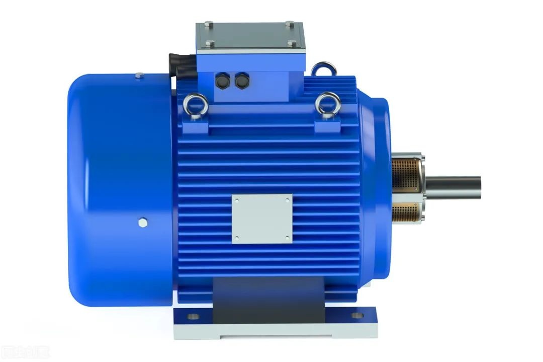

(6) Features:

Since the rotor and the stator rotating magnetic field of the three-phase asynchronous motor rotate in the same direction and at different speeds, there is a slip, so it is called a three-phase asynchronous motor. The rotor speed of the three-phase asynchronous motor is lower than that of the rotating magnetic field. The relative motion between the rotor winding and the magnetic field generates electromotive force and current, and interacts with the magnetic field to generate electromagnetic torque to realize energy conversion.


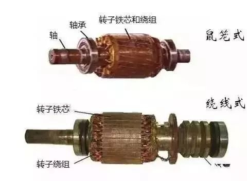
Compared with single-phase asynchronous motors, three-phase asynchronous motors have better running performance and can save various materials. According to different rotor structures, three-phase asynchronous motors can be divided into cage type and wound type. The asynchronous motor with cage rotor has simple structure, reliable operation, light weight and low price, and has been widely used. Its main disadvantage is that it is difficult to adjust the speed.


Ordinary motor VS variable frequency motor
  
1. The difference between ordinary motors and variable frequency motors   

First of all, ordinary motors cannot be used as variable frequency motors. Ordinary motors are designed according to constant frequency and constant voltage, and it is impossible to fully meet the requirements of frequency converter speed regulation, so they cannot be used as variable frequency motors.

(1) The influence of the frequency converter on the motor is mainly in the efficiency and temperature rise of the motor
The frequency converter can generate different levels of harmonic voltage and current during operation, so that the motor operates under non-sinusoidal voltage and current, and the high-order harmonics inside will cause the stator copper loss, rotor copper loss, iron loss and additional loss to increase. , the most notable is the copper loss of the rotor, these losses will cause the motor to generate extra heat, reduce the efficiency, and reduce the output power. The temperature rise of ordinary motors generally increases by 10%-20%.

(2) The insulation strength of the motor
The carrier frequency of the frequency converter ranges from several thousand to more than ten kilohertz, which makes the stator winding of the motor bear a high voltage rise rate, which is equivalent to applying a steep impulse voltage to the motor, and makes the inter-turn insulation of the motor withstand a relatively serious test .

(3) Harmonic electromagnetic noise and vibration
When an ordinary motor is powered by a frequency converter, the vibration and noise caused by electromagnetic, mechanical, ventilation and other factors will become more complicated. The harmonics contained in the variable frequency power supply and the inherent space harmonics of the electromagnetic part of the motor interfere with each other to form various electromagnetic excitation forces, thereby increasing the noise. Due to the wide operating frequency range of the motor and the wide range of rotational speed, it is difficult for the frequency of various electromagnetic force waves to avoid the natural vibration frequency of each structural part of the motor.

(4) Cooling problem at low speed
When the frequency of the power supply is low, the loss caused by the high-order harmonics in the power supply is relatively large; secondly, when the speed of the flexible motor decreases, the cooling air volume decreases proportionally to the cube of the speed, so that the heat of the motor cannot be dissipated, and the temperature rises sharply increase, it is difficult to achieve constant torque output.


2. How to distinguish between ordinary motors and variable frequency motors?

(1) Higher insulation level requirements
Generally, the insulation grade of the frequency conversion motor is F grade or higher, and the ground insulation and the insulation strength of the turns are strengthened, especially the ability of the insulation to withstand the impact voltage should be considered.

(2) The vibration and noise requirements of variable frequency motors are higher
The variable frequency motor should fully consider the rigidity of the motor components and the whole, and try to increase its natural frequency to avoid resonance with each force wave.

(3) The cooling method of the frequency conversion motor is different
The frequency conversion motor is generally cooled by forced ventilation, that is, the cooling fan of the main motor is driven by an independent motor.

(4) Different requirements for protection measures
Bearing insulation measures should be adopted for variable frequency motors with a capacity exceeding 160KW. The main reason is that it is easy to produce magnetic circuit asymmetry and axial current. When the currents generated by other high-frequency components work together, the axial current will increase greatly, resulting in bearing damage, so insulation measures are generally taken. For constant power variable frequency motors, when the speed exceeds 3000/min, special grease with high temperature resistance should be used to compensate for the temperature rise of the bearing.

(5) The cooling system is different
The frequency conversion motor cooling fan is powered by an independent power supply to ensure continuous cooling capacity.


stepper motor
  
A stepper motor is an electromechanical device that directly converts electrical pulses into mechanical motion. By controlling the sequence, frequency and quantity of electrical pulses applied to the motor coil, the steering, speed and rotation angle of the stepper motor can be controlled.

In the absence of a closed-loop feedback control system with position sensing, precise position and speed control can be achieved by using a simple and low-cost open-loop control system composed of a stepper motor and its matching driver.

basic structure:

 
working principle:
According to the external control pulse and direction signal, the stepper motor driver controls the winding of the stepper motor to energize forward or reverse at a certain timing through its internal logic circuit, so that the motor rotates forward/reversely, or locks.

Take a 1.8-degree two-phase stepping motor as an example: when both phase windings are energized and excited, the motor output shaft will be stationary and locked in position. The maximum torque that keeps the motor locked at rated current is the holding torque. If the current in one of the phase windings is reversed, the motor will rotate one step (1.8 degrees) in a given direction.

Similarly, if the current of another winding changes direction, the motor will rotate one step (1.8 degrees) in the opposite direction to the former. When the current passing through the coil winding is excited in sequence, the motor will realize continuous rotation and step along the predetermined direction, and the operation accuracy is very high. For a 1.8-degree two-phase stepper motor, 200 steps are required for one revolution.

Two-phase stepper motors have two types of windings: bipolar and unipolar. There is only one winding coil on each phase of the bipolar motor. When the motor rotates continuously, the current must be excited in the same coil in turn. The design of the drive circuit requires eight electronic switches to switch sequentially.

There are two winding coils with opposite polarities on each phase of the unipolar motor. When the motor rotates continuously, it only needs to alternately energize and excite the two winding coils on the same phase. Only four electronic switches are required in the drive circuit design. In the bipolar driving mode, since the winding coil of each phase is 100% excited, the output torque of the motor in the bipolar driving mode is increased by about 40% compared with that in the unipolar driving mode.


Motor selection procedure
  
The basic contents required for motor selection include: the type of load driven, rated power, rated voltage, rated speed, and other conditions.

load type
For production machinery with stable load and no special requirements for starting and braking, the continuous operation of production machinery should preferably use ordinary squirrel-cage asynchronous motors, which are widely used in machinery, water pumps, fans, etc.


Starting and braking are relatively frequent, and production machinery that requires a large starting and braking torque, such as bridge cranes, mine hoists, air compressors, irreversible rolling mills, etc., should use wound asynchronous motors.
Where there is no requirement for speed regulation, where constant speed is required or power factor improvement is required, synchronous motors should be used, such as medium and large capacity water pumps, air compressors, elevators, mills, etc.

The speed regulation range is required to be above 1:3, and the production machinery that requires continuous, stable and smooth speed regulation should use separately excited DC motors or squirrel-cage asynchronous motors or synchronous motors with frequency conversion speed regulation, such as large precision machine tools, gantry planers, Rolling mills, elevators, etc.

For production machinery that requires large starting torque and soft mechanical characteristics, use series-excited or compound-excited DC motors, such as trams, electric locomotives, and heavy cranes.

Generally speaking, the motor can be roughly determined by providing the type of load driven, the rated power, rated voltage, and rated speed of the motor. But these basic parameters are not enough if the load requirements are to be met optimally. The parameters that need to be provided include: frequency, working system, overload requirements, insulation level, protection level, moment of inertia, load resistance moment curve, installation method, ambient temperature, altitude, outdoor requirements, etc., according to specific conditions.


Summary of Motor Fault Handling Experience
  
When the motor is running or fails, four methods can be used to prevent and eliminate the fault in time to ensure the safe operation of the motor.

  one look   
Observe whether there is any abnormality during the operation of the motor, which is mainly manifested in the following situations.
1. When the stator winding is short-circuited, you may see smoke from the motor.
2. When the motor is seriously overloaded or running without phase, the speed will slow down and there will be a heavy "humming" sound.
3. The motor maintenance network is running normally, but when it stops suddenly, you will see sparks from the loose wiring; the fuse is blown or a part is stuck.
4. If the motor vibrates violently, it may be that the transmission device is stuck, the motor is not fixed properly, or the anchor bolts are loose.
5. If there are discoloration, burn marks and smoke traces at the contact points and connections in the motor, it may indicate local overheating, poor contact at conductor connections, or burnt windings.

  Two, listen   
When the motor is running normally, it should emit a uniform and light "hum" sound, without noise or special sound. If there is too much noise, including electromagnetic noise, bearing noise, ventilation noise, mechanical friction sound, etc., it may be a precursor or phenomenon of failure.
1. For electromagnetic noise, if the motor makes a high and low and heavy sound, there may be the following reasons:
(1) The air gap between the stator and the rotor is not uniform. At this time, the sound fluctuates and the interval between high and low sounds remains unchanged. This is caused by the wear of the bearings and the non-concentricity of the stator and the rotor.
(2) The three-phase current is unbalanced. This is due to misgrounding, short circuit or poor contact of the three-phase windings. If the sound is dull, it means that the motor is seriously overloaded or running with a lack of phase.
(3) The iron core is loose. During the operation of the motor, the fixing bolts of the iron core are loosened due to vibration, resulting in the loosening of the silicon steel sheet of the iron core and making noise.
2. For bearing noise, it should be monitored frequently during the operation of the motor. The monitoring method is: put one end of the screwdriver against the bearing installation part, and the other end close to the ear, and you can hear the sound of the bearing running. If the bearing is in normal operation, the sound will be a continuous and small "rustling" sound, without fluctuating highs and lows and metal friction sounds.

It is abnormal if the following sounds appear: 
(1) There is a "squeak" sound when the bearing is running. This is the metal friction sound, which is generally caused by the lack of oil in the bearing. The bearing should be disassembled and filled with proper amount of grease.
(2) If there is a "chirp" sound, this is the sound made when the ball rotates. Generally, it is caused by dry grease or lack of oil, and an appropriate amount of grease can be added.
(3) If there is a "click" or "creak" sound, it is the sound produced by the irregular movement of the balls in the bearing. This is caused by the damage of the balls in the bearing or the long-term use of the motor and the dryness of the grease.
3. If the transmission mechanism and the driven mechanism make continuous sound instead of fluctuating high and low, it can be dealt with in the following situations.
(1) The periodic "crack" sound is caused by the unevenness of the belt joint.
(2) The periodic "booming" sound is caused by the looseness between the coupling or the pulley and the shaft and the wear of the key or keyway.
(3) The uneven collision sound is caused by the blades colliding with the fan cover.

  Three, smell    
Faults can also be judged and prevented by smelling the smell of the motor. Open the junction box and sniff. Check to see if there is a burnt smell. If you find a special smell of paint, it means that the internal temperature of the motor is too high; if you find a strong smell of burnt or burnt smell, it may be that the insulation layer has been broken down or the winding has been burned. If there is no smell, it is necessary to use a megohmmeter to measure that the insulation resistance between the winding and the casing is lower than 0.5 megabytes, and it must be dried. If the resistance is zero, it means it is damaged.

  Four, touch    
The cause of the fault can also be judged by touching the temperature of some parts of the motor. In order to ensure safety, the back of the hand should be used to touch the motor casing and the parts around the bearing. If the temperature is found to be abnormal, the reasons may be as follows.
1. Poor ventilation. For example, the fan falls off, the ventilation channel is blocked, etc.
2. Overload. As a result, the current is too large and the stator windings are overheated.
3. Turn-to-turn short circuit of the stator winding or unbalanced three-phase current.
4. Frequent starting or braking.
5. If the temperature around the bearing is too high, it may be caused by bearing damage or lack of oil.
Motor bearing temperature regulations, abnormal causes and treatment
The regulations stipulate that the maximum temperature of rolling bearings does not exceed 95°C, and the maximum temperature of sliding bearings does not exceed 80°C. And the temperature rise shall not exceed 55°C (the temperature rise is the bearing temperature minus the ambient temperature during the test);
For details, see HG25103-91 Reasons and solutions for excessive bearing temperature rise:
(1) Reason: The shaft is bent and the center line is not allowed.
Process; re-center.
(2) Reason: The foundation screws are loose.
Treatment: Tighten the foundation screws.
(3) Reason: The lubricating oil is not clean.
Treatment: replace the lubricating oil.
(4) Reason: The lubricating oil has been used for too long and has not been replaced.
Treatment: Clean the bearings and replace the lubricating oil.
(5) Reason: The ball or roller in the bearing is damaged.
Treatment: replace the new bearing.