


Assembly process of small and medium motors
01
Stator assembly
Most of the motor factories in China use the external press-fitting process when producing small motors. After the stator core is dipped and baked, the axial position must meet the requirements of the drawing when it is pressed into the frame, otherwise one end of the coil will stretch too much, resulting in difficulty in assembly, and it will increase the air gap magnetic potential of the motor , affecting the motor performance. At the same time, the axial force wear on the rotor will be aggravated. The axial position of the stator core in the frame is generally guaranteed on the press-fit tire. As shown in Figure 7-7, control the size of the pressing cap so that the position of the iron core after pressing meets the requirements of the drawing. The method of determining the size is to ensure that the stator core does not rotate in the machine base after the press-fitting is completed. It is not enough to rely solely on the contact between the inner circle of the machine base and the outer circle of the stator core, so each motor must be installed with a stopper. Screws, so that the core is completely fixed on the frame.
02
Rotor assembly
The rotor assembly of the asynchronous motor includes the assembly of the rotor core and the shaft, the assembly of the bearing and the assembly of the fan.
1
Assembly of rotor core and shaft
●
When the motor is running, it needs to output mechanical power through the rotating shaft. Therefore, the reliability of the combination of the rotor core and the shaft is very important. When the outer diameter of the rotor is less than 300mm, the rotor core is generally pressed directly on the shaft; when the outer diameter of the rotor is greater than 300mm to 400mm, the rotor bracket is first pressed into the core, and then the shaft is pressed into the rotor bracket. The Y series motor adopts the structure that the rotor core is directly pressed on the shaft. There are three basic forms of assembly of rotor core and shaft: knurled cold press fit, shrink fit and key connection fit.
-
Knurled cold press fit In the knurled cold press fit, the processing technology of the shaft is: finish car core gear, knurling and grinding, then press into the rotor core, and then fine grind the shaft extension, bearing gear and the outer circle of the finish car core . When using the knurling process, excessive interference is not allowed. Because the size of the cold pressing pressure is directly proportional to the amount of interference, when the amount of interference is too large, it may not be pressed in, or the internal stress of the material is too large to deform or break.
-
Shrink fitting generally uses the residual heat of the rotor after casting aluminum (or reheating the rotor) for heat fitting. The cold pressing equipment can be saved by adopting the heat-shrinking process, and at the same time, the combination of the rotor core and the shaft is more reliable. Because the heat sleeve heats and expands the containing part and then cools down, the hole of the containing part shrinks and hugs the contained part, which ensures sufficient interference value and high reliability.
-
The advantage of the key connection is that it can ensure the reliability of the connection and facilitate the organization of flow production; the disadvantage is that the processing steps increase, and opening the keyway on the shaft will reduce the strength of the shaft, especially in small motors. When connecting with keys, the width of the keys shall be selected according to the specified requirements. In order to simplify the process, usually the same keyway width can be used with the shaft extension.
2
Bearing assembly
●
In small and medium-sized asynchronous motors, rolling bearing structures are widely used. It is lighter than sliding bearings, does not require frequent maintenance during operation, and consumes less lubricating grease. At the same time, the radial clearance of the rolling bearing is small, which is more suitable for the asynchronous motor with a small air gap.
03
Assembly
The general assembly of small and medium-sized motors includes inserting the rotor into the stator, installing other components, such as end covers, junction boxes, external fans and brush devices, etc. After the final assembly, tests and motor appearance modification are required.
1
The rotor is inserted into the stator assembly
●
Inserting the rotor into the stator is one of the key processes. Improper operation can easily cause damage to the winding, and sometimes even deformation of the shaft. When fitting, it is also necessary to pay attention to the corresponding position of the shaft extension and the junction box. When the mass of the rotor is less than 35kg, it can be inserted into the stator by hand. Larger rotors require lifting tools. During operation, first lift the tool at the ring 2, put it on the rotor shaft, then lift the rotor at the ring 1, and hold the joystick 3 to make the rotor penetrate into the stator horizontally and smoothly.
2
Install the end cap
●
When installing the end cover, generally install the non-shaft extension end first. Apply a thin layer of engine oil to the assembly seam to prevent the mouth from rusting. After installing the end cover into the seam, tap the surroundings of the end cover to make the end cover close to the end face of the machine base, and then tighten the bolts diagonally and alternately. When installing the second end cover, the rotor needs to be hoisted (the small motor can not be hoisted), then the end cover is knocked closed, and the bolts are tightened. If the end caps at both ends are installed on different axes, or if the end faces are not parallel, the rotor may rotate sluggishly. It is necessary to tap the surroundings of the end caps with a hammer to eliminate the phenomenon of different axes and non-parallelism, so that the rotor can rotate flexibly. Then install the outer bearing cover and tighten the bearing cover screws.
3
Air gap adjustment
●
For medium-sized motors with full-round end cover rolling bearings, when the rotor is inserted into the stator, the end cover at the ball bearing end should be installed first, and then the end cover at the roller bearing end to prevent the rolling bearing from being damaged. When the end cover of the ball bearing end must be installed first, the screw of the end cover should not be tightened, and the screw should be tightened after the end cover of the ball bearing is installed. After the end cover is installed, the air gap should be adjusted. The method of adjustment is to use jacks (four at both ends) to adjust the relative position of the end caps. Use a feeler gauge to measure at positions with a mutual difference of 120° (both ends) until the uniformity of the air gap meets the standards specified in the technical conditions. After adjusting the air gap, tighten the screws, drill the positioning pin holes on the horizontal punching machine according to the position specified in the pattern, and punch the positioning pins.
4
Assembly of the brush system
●
In motors with slip ring contacts (such as large and medium-sized wound rotor asynchronous motors), the quality of brush assembly has a great influence on the conduction; in motors with commutators, the commutation of the motor Good or bad, it is often closely related to the assembly quality of the brush system.
Brushes for collector rings and commutators are generally electrochemical graphite brushes and metal graphite brushes. Electrochemical graphite brushes are made of natural graphite after processing to remove impurities and then sintered. According to the ratio of raw materials, it can be divided into graphite-based, coke-based and carbon black-based. The brush resistivity and contact pressure drop of carbon black base are relatively high, which is suitable for motors with difficult commutation; graphite base is often used for normal motors. Electrochemical graphite brushes have low hardness and slow wear, and the current density is generally selected at 10 -12A1cm 2 . Metal-graphite brushes are suitable for low-voltage, high-current motors, which are mixed and sintered by adding 40% -50% copper powder into graphite. It has high density, low hardness, small wear resistance coefficient, low resistivity coefficient, low contact pressure drop, and slow wear. The current density is generally selected at 17 -20A/cm 2 .
The arrangement of the brushes is in the DC motor, because the degree of wear of the commutator under the positive and negative brushes is inconsistent, so the position of the arrangement of the brushes must be arranged reasonably. The brushes should be staggered on the surface of the commutator.
04
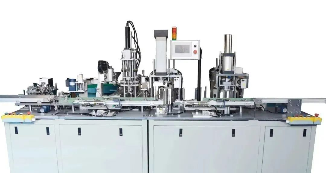
Small motor assembly automation
In order to improve labor productivity, reduce production cost, shorten product development or production cycle, and enhance the market competitiveness of products, domestic and foreign motor industries are competing to introduce technology in the field of motor assembly. The early motor assembly automation system, represented by the semi-automatic motor assembly line, was used for the assembly of small motors with large quantities and small specifications. This semi-automatic assembly line includes assembly machinery such as automatic rotor assembly machine, bearing press assembly machine, end cover press assembly machine, and screw tightening machine. And tighten the butterfly and nail. The main assembly process is completed by machinery, and the auxiliary work is completed manually. The equipment of this semi-automatic assembly line is fixedly installed, has a certain working rhythm , and has high working efficiency, which can reach 25-40s/set.
In order to meet the automatic assembly requirements of multi-variety and small-batch products, foreign countries have successively developed flexible assembly cells (FAC) and flexible assembly systems (FAS), both of which use computer-controlled robots as core equipment, so they all have a high level of automation. The flexible assembly unit includes a handling robot and multiple assembly robots. The handling robot is responsible for the handling of various parts, and sends the assembled parts to the workstation of the assembly robot in sequence, and then moves the assembled parts to the conveyor belt and sends them away. The assembly robot is equipped with equipment such as a workbench and a press, and is responsible for the assembly of various components. The flexible assembly unit can assemble different types of components, and can also change the computer program to assemble motor products of different specifications.
On the basis of the flexible assembly unit, a fully automated flexible assembly system has been further developed. This system mainly includes several parts such as programmable assembly unit, system storage warehouse and flexible logistics transmission system, and its core is programmable assembly unit. The programmable assembly unit realizes the control of the assembly robot by changing the computer program, and assembles various motors of different specifications. In order to ensure unobstructed supply of components to the assembly system and to act as a buffer in the event of a system failure, the flexible assembly system has a storage warehouse. There is a programmable shelf control device in the warehouse, so that the computer can conduct random access to each storage unit. The flexible logistics transmission system consists of a conveyor belt or an automatic guided vehicle (AGV), which is responsible for the handling of materials and the exchange of logistics between processes inside and outside the system. The automatic guided vehicle is flexible and unrestricted, and the parking accuracy is very high (up to ±1mm), so it has become the main equipment of the flexible transmission system. The FAS system usually adopts a hierarchical distributed computer control system to manage and control various automation equipment in the system. The computer system includes a main computer, a FAS management computer, a logistics computer and multiple FAC computers.
Through these computers, the FAS system can easily change the program and control the assembly system to realize the automatic assembly of multi-specification motors. Taking an automatic assembly system developed abroad as an example, it can realize the automatic assembly of 450 small motors of different specifications. It can be seen that the FAS flexible assembly system not only has a high degree of automation, but also has a strong adaptability. It is the direction of today's small motor assembly automation. In addition to assembly automation, there are also motor factory test automatic lines and electrostatic spray painting automatic lines. The use of these automatic lines will greatly improve labor conditions and labor productivity, and create favorable conditions for realizing unmanned
 XINDA
XINDA