


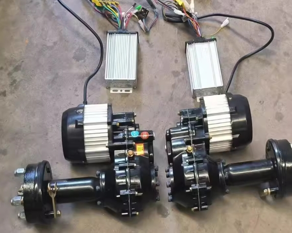


Motor drive system function and principle
The driving motor and the driving motor controller are the core components in the driving system of new energy vehicles, which determine the main performance indicators of the vehicle, and play an important role in the driving performance, economy, safety, and stability of the new energy vehicle. Impact.
The motor controller obtains the torque demand of the vehicle from the vehicle controller, obtains electric energy from the power battery pack, and obtains the current and voltage required to control the motor through the modulation of its own inverter, and provides it to the motor, so that the speed and rotation speed of the motor The torque meets the driving needs of the whole vehicle.
1. Drive motor
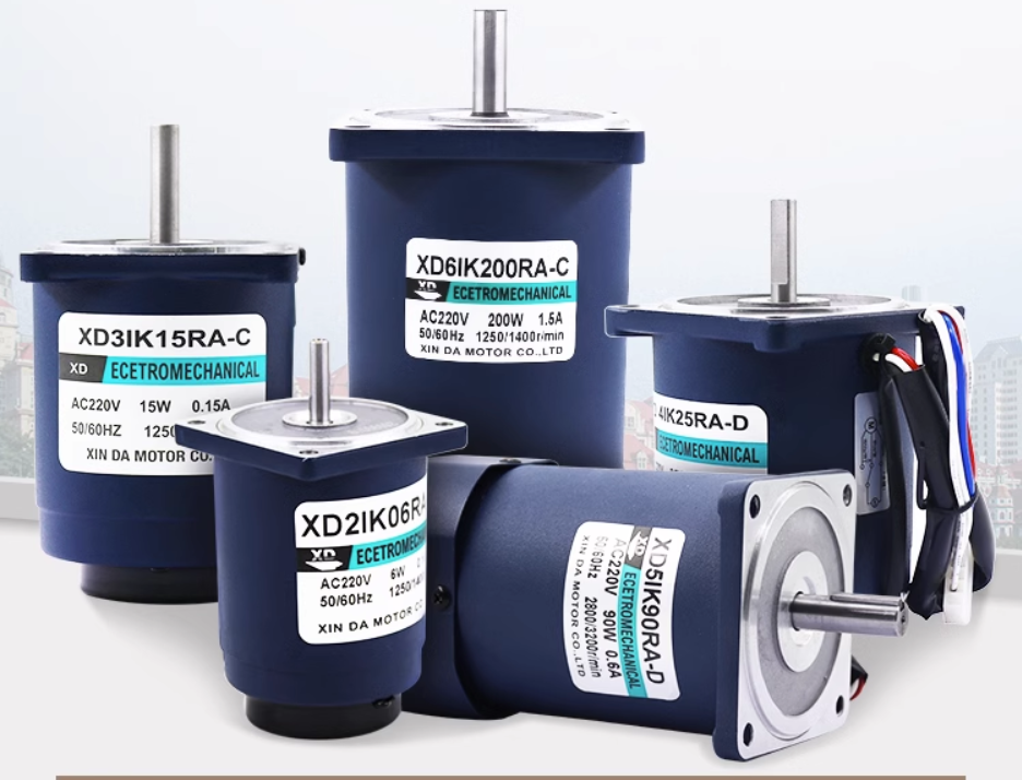
(1) Composition and function of drive motor
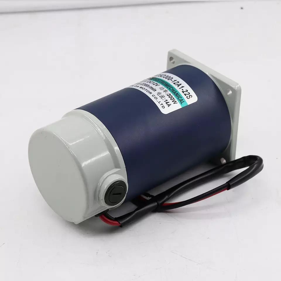
Permanent magnet synchronous motors are divided into sine wave permanent magnet synchronous motors and square wave driven permanent magnet synchronous motors.
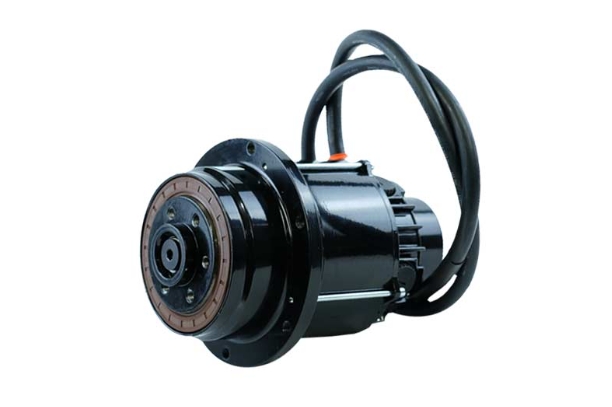
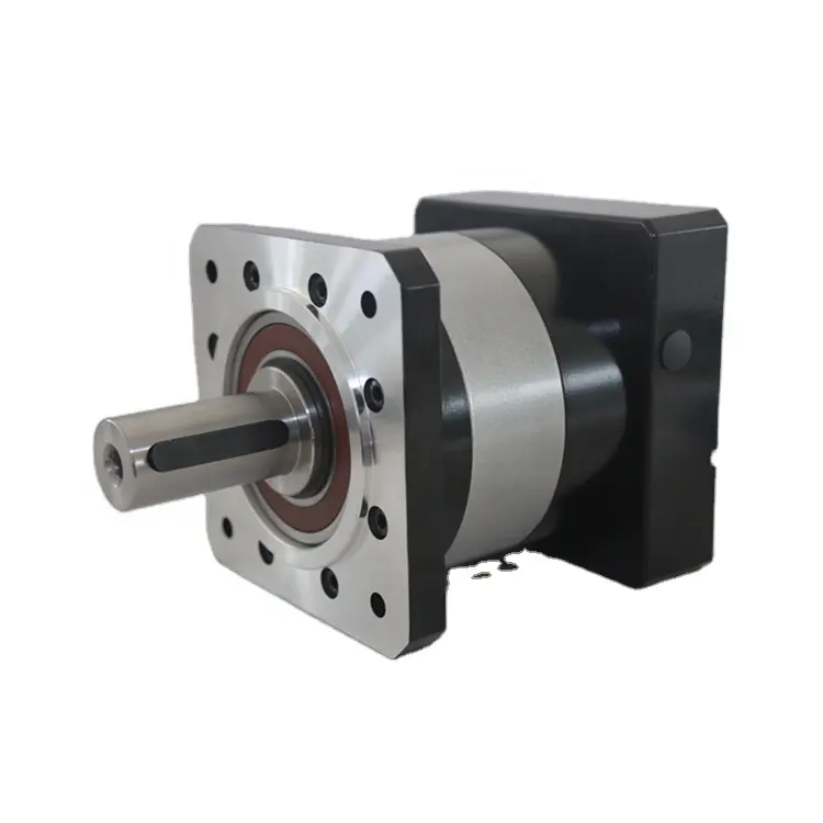
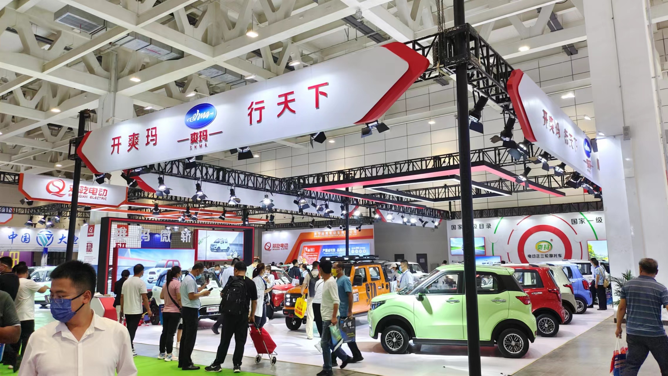
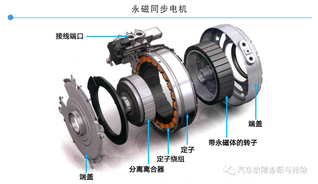
The permanent magnet synchronous motor is mainly composed of stator and rotor, end cover, bearing, resolver and other components.
(2) Working principle of permanent magnet synchronous motor
The permanent magnet in the permanent magnet synchronous motor means that the rotor of the motor is a permanent magnet (permanent magnet). Synchronization means that the frequency of the rotor is the same as that of the stator. The motor refers to a device that converts electrical energy into mechanical energy.
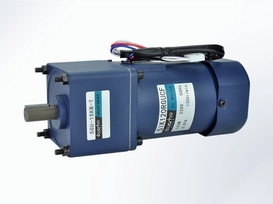
The permanent magnet synchronous motor rotates the magnetic field of the outer ring through the method of electric rotation. When the magnetic field of the outer ring of the stator rotates, the permanent magnet of the rotor inside can follow the rotation through the principle of opposite sex attraction and same sex repulsion of the magnetic field.
On the basis of his predecessors, Nicola Truss innovatively used alternating current in the coil, and obtained an alternately variable magnetic field through the phase angle difference of the alternating current in the coil.
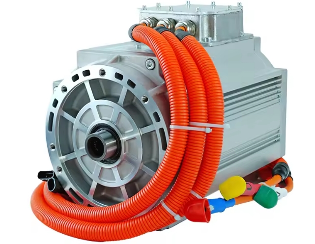
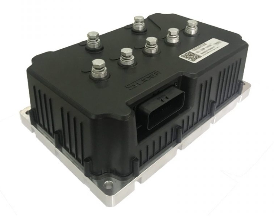
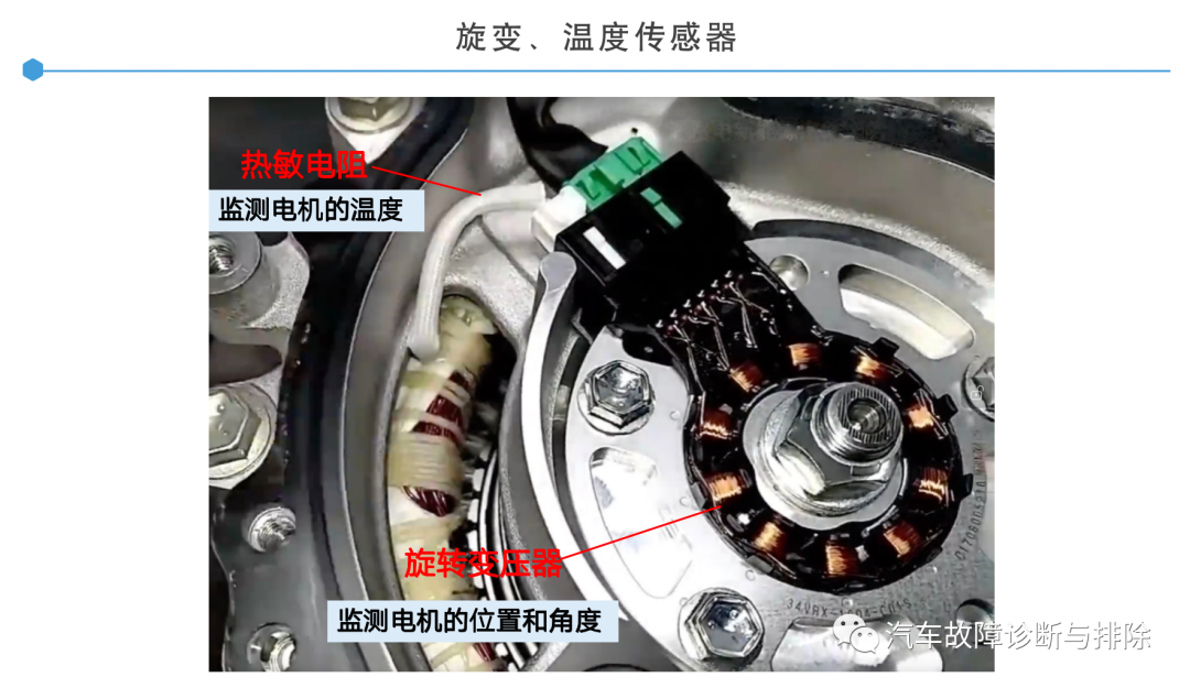
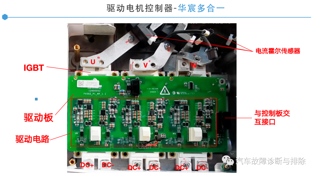
(1) Drive motor controller structure
The motor controller contains 1 inverter (DC/AC) and 1 DC converter (DC/DC); the inverter is composed of IGBT, DC bus capacitor, drive and control circuit board to realize DC (variable Voltage, current) and alternating current (variable voltage, current, frequency). The DC converter is composed of high and low voltage power device transformers, inductors, drive and control circuit boards, etc., to realize the energy transfer from DC high voltage to DC low voltage. The motor controller also contains a cooler (via coolant) to dissipate heat from the power electronics.
The motor controller is installed in the front cabin and adopts CAN communication control to control the energy transmission between the power battery pack and the motor. At the same time, it collects the motor position signal and three-phase current detection signal to precisely control the operation of the driving motor.
The motor controller is a device that can not only convert the DC power in the power battery into AC power to drive the motor, but also convert the kinetic energy of the wheel rotation into electrical energy (AC power into DC power) to charge the power battery.
Its main principle is: the motor is powered on, generates current, and builds a magnetic field. Alternating current produces an alternating magnetic field, and when the windings are arranged at a certain angle in physical space, a circular rotating magnetic field will be generated. The movement is relative, which means that the magnetic field is cut by the conductor within its spatial range, so an induced electromotive force is established at both ends of the conductor, and a loop is formed through the conductor itself and the connecting parts, generating a current and forming a current-carrying conductor . The current-carrying conductor will experience a force in the rotating magnetic field, which eventually becomes the force in the output torque of the motor.
When the electric vehicle decelerates and brakes, that is, when the power supply is cut off, the motor of the electric vehicle rotates inertially. At this time, through circuit switching, a comparatively small power excitation power is provided to the rotor to generate a magnetic field. The magnetic field passes through the physical structure of the rotor. Rotate and cut the winding of the stator, so the stator induces an electromotive force, which is also a reverse electromotive force. At this time, the motor is equivalent to the function of a generator, and the generated current is connected to the battery through a power converter, which is energy feedback. So far, the braking energy is recovered. The process is complete.
(3) Working characteristics
The VCU calculates the motor torque command request signal according to the accelerator pedal position, brake and gear position, and the torque limit signal received from each system.
drive
In driving READY (OK), the VCU controls the MCU to drive the vehicle through the target torque.
brake priority
When the VCU detects that the accelerator pedal APS and brake pedal BPS input signals are simultaneously valid, the braking function takes priority, and the VCU only responds to the braking request.
charging stop
When it is detected that any charging connection signal of fast charging or slow charging is valid, and the motor speed is less than the set value, the VCU controls the motor controller torque output to be 0 all the time, and at the same time sends the MCU enable to be 0.
Motor system torque control
After the driving high-voltage power-on is completed, the VCU sends an enable signal to the MCU, and the vehicle enters the drive-ready state.
The VCU calculates the driver's requested torque based on the accelerator pedal opening signal, brake pedal, gear position signal, vehicle speed signal (motor speed signal), battery status, and motor status.
The VCU sends the positive and negative signals of the motor and the torque command signal to the MCU through CAN information, and the MCU controls the motor to drive the vehicle.
 XINDA
XINDA