


Design specifications for permanent magnet synchronous motors for vehicles
1 Overview
The design of permanent magnet synchronous motors for automobiles is closely related to multiple disciplines such as electricity, magnetism, force, and heat. The motor design process mainly includes five parts: electromagnetic design, structural design, heat dissipation design, insulation design, and component selection. In addition, the cost, weight, and volume of the motor need to be considered, as well as the corresponding vibration, noise and fatigue analysis of the motor.
2 Installation interface design
( 1 ) The motor end cover has a mounting spigot, which is connected to the reduction box through the rotating shaft, and the structure should be compact and easy to arrange;
( 2 ) The design of the high and low voltage interface of the motor should facilitate the assembly of the wiring harness and meet the design requirements of the whole vehicle;
( 3 ) The drive motor is installed on the frame through suspension, and the motor housing and end cover should have suspension points and be reasonably arranged;
( 4 ) Cooling system interface, designed according to customer requirements.
3 Logo design
3.1 Line end identification
The three-phase terminal marks of the motor winding are U , V , W respectively, and there should be permanent marks of U , V , W on the motor casing , and the sequence is U , V , W.
3.2 Nameplate identification
( 1 ) The motor nameplate should include: a ) Manufacturer name; b ) Model, serial number, name; c ) Main parameters: rated power, rated voltage, rated speed, number of phases, duty cycle, peak power, maximum speed, Insulation class, protection class.
( 2 ) There is a clear steel stamp on the motor housing, and the content of the steel stamp consists of the motor model, date and serial number.
( 3 ) The water inlet and outlet of the motor should have water inlet and outlet signs.
3.3 Safety signs
The safety signs are arranged reasonably, not easy to be scratched and damaged, and the high-voltage power connection position is clearly visible. The warning sign of "Beware of Electric Shock" should be set up in a conspicuous position in accordance with the provisions of "GB 18384-2020 Safety Requirements for Electric Vehicles", and in the " Beware of electric shock" warning signs indicate the necessary safety tips.
4 Environmental requirements
( 1 ) Ambient temperature: The permanent magnet synchronous motor should be able to work normally within the range of -40 ℃ ~ 85 ℃;
( 2 ) Humidity: The motor can work normally when the relative humidity does not exceed 100% . The motor should work safely when the surface humidity is lower than the dew point and condensation occurs on the surface of the motor.
( 3 ) Altitude: not more than 1000m , if it exceeds 1000m , it should follow the relevant regulations of GB755-2008 .
5 work system requirements
Vehicle drive motors should meet the S9 working system, that is, the working system with non-periodical changes in load and speed within the allowable range.
6 electromagnetic design
Electromagnetic design According to the requirements of motor design parameters, electromagnetic calculation is carried out to determine the punching size, iron core length and electromagnetic performance of the motor. It mainly consists of four parts: stator punching design, rotor punching design, winding design, and permanent magnet design.
6.1 Calculation of main dimensions
The main dimensions of the motor refer to the motor rotor outer diameter D 2 (or stator inner diameter D i1 ) and length L ef . When the motor is working, the energy is transmitted and converted in the form of electromagnetic energy through the air gap between the stator and rotor. The power transmitted by the air gap is called electromagnetic power P. The electromagnetic power of the AC motor is related to the power factor. The power factor is a variable. The motor It is converted into calculated power P ' during design .
The main size of the motor is determined by the ratio P ' /n of the calculated power P ' to the speed n , and is related to the electromagnetic load A and the air gap magnetic density B δ . When the electromagnetic load A and B δ are constant, the motor with the same power has a higher speed and smaller size; the motor with the same size has a higher speed and higher power. When the speed is constant, if the diameter of the rotor iron core is constant, if the length of the rotor iron core is different, motors with different powers can be obtained.
Reasonable selection of motor length-to-diameter ratio mainly considers the following factors:
( 1 ) Parameters and temperature rise;
( 2 ) save the amount of copper used in the winding;
( 3 ) The mechanical strength of the rotor;
( 4 ) Restrictions on moment of inertia, etc.
For salient pole synchronous motors, the aspect ratio generally increases with the number of poles .
6.2 Selection of electromagnetic load
When selecting the electromagnetic load, a series of factors such as the motor insulation level, the performance of conductive and magnetic permeable materials, the number of poles, power, cooling conditions and performance requirements must be considered. The selection of electric load A (also known as armature line load) and magnetic load B δ value not only affects the size of the motor, but also has a great influence on the parameters, performance and life of the motor.
6.2.1 When the magnetic load B δ is fixed, and the electric load A is selected higher, the following effects will occur:
( 1 ) The main size of the motor decreases with the increase of A value, thus reducing material consumption;
( 2 ) Since B δ is constant, the iron loss will decrease with the reduction of core material.
( 3 ) The amount of B δ copper (aluminum) used for winding , copper (aluminum) loss and temperature rise increase, and the efficiency decreases.
( 4 ) When the line load A is selected higher, the leakage reactance increases, resulting in a decrease in the maximum torque and starting torque. This is because the increase of A value increases the number of series turns of each phase of the stator winding, which increases the leakage reactance of the motor in direct proportion to the square of the number of turns.
(5) When the value of A is larger, the power factor of the motor is improved.
6.2.2 When the electric load A is fixed and the magnetic load B δ is selected higher, the following effects will occur:
( 1 ) The main size of the motor decreases with the increase of B δ , thus saving effective materials;
( 2 ) As the B δ value increases, the magnetic flux density in the iron core increases, and the iron loss increases approximately proportional to the square of the magnetic density, resulting in a decrease in the efficiency of the motor;
( 3 ) As the air gap and the magnetic flux density in the iron core increase, the magnetizing current increases and the power factor decreases;
( 4 ) The increase of B δ value will reduce the leakage reactance of the motor, causing the starting current to increase.
During the initial design of the scheme, the electromagnetic load is selected based on the data accumulated from manufacturing and operating experience.
For small and medium-sized permanent magnet synchronous motors, the line load is usually ( 1.5 × 10 4 ~ 5 × 10 4 ) A/m , and the air gap magnetic density is in the range of 0.6T ~ 0.8T . The specific selection is related to various factors such as the performance of the electrical materials used, the insulation level and the number of pole pairs, power, cooling conditions, performance requirements and operating conditions.
6.3 Selection of Motor Air Gap Length
The air gap length of the motor greatly affects the performance, reliability, assembly difficulty and manufacturing cost of the motor. From the perspective of the electromagnetic performance of the permanent magnet synchronous motor, the smaller the air gap length, the larger the power factor of the motor, the higher the efficiency of the motor, the higher the torque density, and the wider the speed range of the motor's field weakening. However, the harmonic component of the air gap magnetic field increases, and the motor is prone to vibration and noise. At the same time, the stray loss of the motor increases. If the air gap length is too small, it is difficult to ensure the coaxiality of the motor during operation, which will easily lead to The phenomenon of motor sweeping reduces the reliability of motor operation, and at the same time increases the difficulty of motor assembly.
The air gap length of permanent magnet synchronous motor should consider the following factors when designing:
( 1 ) In order to reduce the excitation current and improve the power factor, the air gap should be as small as possible;
( 2 ) The air gap is small, the harmonic magnetic field and harmonic leakage reactance increase, which reduces the starting torque, increases the stray loss, and may increase the temperature rise;
( 3 ) In order to ensure the reliable operation of the motor and avoid friction between the stator and rotor due to uneven air gap, the air gap should not be too small.
6.4 Selection of number of stator slots
In motor design, as the ratio of slot poles increases, the inner diameter of the motor stator remains unchanged. Due to the increase in the insulation volume in the slot, the outer diameter of the motor increases, the volume of the motor increases, the copper used at the end increases, and the mass of the motor increases, but the magnetic field of the motor winding The sine degree of the motive force increases, the ripple torque of the motor decreases, the torque ripple decreases, and the iron loss decreases. At the same time, the sine degree of the back EMF of the winding increases, and the harmonic content decreases, but the fundamental winding factor decreases, and the output torque of the motor decreases. Reasonably select the motor slot-to-pole ratio to adjust the motor efficiency and external characteristics.
As the slot-to-pole ratio of the motor increases, the width of the stator tooth portion of the motor decreases. Due to the torque ripple and electromagnetic radial force during the operation of the motor, the motor will vibrate. If the stator tooth portion is too narrow, the mechanical strength of the stator tooth portion will be poor. , resulting in broken stator teeth. In addition, the increase in the number of slots per pole and phase will cause a substantial increase in the manufacturing cost of the stator, which will affect the economical efficiency of the motor and make it difficult to wind the stator winding. At the same time, the slot width of the stator is optimized to reduce the limit of the motor torque ripple increase.
When the number of poles and phases is given, the number of slots of the stator is determined by the number of slots q per pole and phase .
6.5 Winding design
The composition of the stator winding should comply with the following basic principles:
( 1 ) The three-phase windings of A , B and C should be symmetrical, with a phase difference of 120 degrees;
( 2 ) During the operation of the permanent magnet synchronous motor, the air gap flux density and back EMF waveform should have a higher sine degree, so that the harmonic content is as small as possible;
( 3 ) The amount of copper used in the winding should be as little as possible;
( 4 ) The processing technology, assembly and maintenance of the winding should be simple.
Reasonably choose the winding method to reduce the winding length of the motor end, reduce the length of the motor and the amount of copper used, reduce the copper loss of the motor, and improve the efficiency of the motor, thereby reducing the length of the motor, reducing the volume of the motor, and reducing the quality of the motor. The power density of the motor is greatly improved.
Reasonable selection of the motor winding winding method can increase the sine degree of the magnetic potential of the stator winding, reduce the harmonic content of the stator magnetic potential, reduce the iron loss of the motor and the ripple torque of the motor caused by the stator winding, improve the efficiency of the motor, and reduce the vibration and vibration of the motor. noise. In addition, a reasonable selection of the motor winding winding method can increase the saliency of the motor, increase the reluctance torque, reduce the winding current, reduce the copper consumption of the motor, and improve the efficiency of the motor.
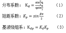
After selecting the number and pitch of each pole and each phase, the fundamental winding coefficient can be obtained according to the following formula .
6.6 Stator slot size
In the design of the motor, the existence of the slot width greatly changes the effective air gap between the stator and the permanent magnet magnetic field, and then causes a drastic change in the air gap permeability, which affects the leakage inductance of the permanent magnet synchronous motor and makes the air gap magnetic field The dense surface shows a sawtooth waveform, which produces cogging torque, which causes torque ripple and noise during the operation of the motor, which affects the ride comfort of new energy vehicles.
As the opening width of the stator slot increases, the equivalent air gap length of the motor increases, the leakage inductance of the winding decreases, the air gap flux density of the motor decreases, the salient pole ratio of the motor decreases, the reluctance torque utilization rate decreases, and the field weakening effect decreases. Motor torque density is reduced. However, if the opening width of the stator slot is too small, it is difficult to insert the wire of the motor winding. Properly reducing the opening width of the stator slot without affecting the insertion of the motor is beneficial to the improvement of the power density of the motor. In addition, reasonable selection of the opening width of the stator slot of the motor can reduce the cogging torque of the motor to a certain extent, and reduce the vibration and noise of the motor.
In the design of the motor stator groove structure, the reluctance of the motor stator magnetic circuit should be optimized, there is no magnetic density singularity in the stator magnetic circuit, and the operating point of the permanent magnet is located near the optimal operating point within the operating range of the motor. At the same time, the choice of stator groove type should be conducive to the embedding of the motor.
Finally, the fullness of the stator slot should be increased as much as possible without affecting the embedding process.
6.7 Selection of pole pairs
The number of pole pairs should be based on the hardware design of the control system, the simulation of the motor temperature rise system and the prototype experiment, and based on factors such as the output frequency of the controller, the material mode of the power system, the limit value of the motor temperature rise, efficiency, and the gear ratio of the reducer. choose.
With the increase of the number of pole pairs of the motor, the amount of iron used in the yoke of the stator core of the motor decreases, and the volume of the motor decreases. Due to the increase of the stator insulating material, the speed of the volume reduction of the motor gradually decreases. With the increase of the number of pole pairs of the motor, the frequency of the input current of the motor increases, the iron consumption of the motor increases, and the efficiency decreases. At the same time, the requirements for the motor control system and the motor cooling system are increased.
In the design of high-speed motors, the number of motor pole pairs is generally selected to be small. When the number of pole pairs of the motor is less than 5 , the outer diameter of the motor stator changes drastically with the number of pole pairs of the motor, and when the number of pole pairs is greater than 5 , the outer diameter of the stator changes slowly. Since the motor adopts a high-speed and low-torque design, in order to meet the effective requirements of the control system Increase the current output frequency and reduce the iron loss in the motor at the same time. Generally, the number of pole pairs of permanent magnet synchronous motors is 4 .
6.8 Rotor topology
Rotor topology: V -shaped ( a ), double-shaped ( b ), inverted triangle ( c/d ), double- V- shaped ( e ).
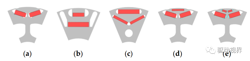
Figure 1 : Built-in rotor topology
There are five main rotor topologies of built-in permanent magnet synchronous motors as shown in the figure above.
The dimensions of the permanent magnet mainly include the magnetization direction length h m and the width b m . The design of permanent magnets should consider the following factors:
(1) The determination of h m should make the direct axis reactance X ad of the motor reasonable.
(2) h m cannot be too thin. One is that too thin h m will lead to an increase in the scrap rate of permanent magnet production, and the cost of permanent magnets will increase; the other is that too thin permanent magnets will make it easy to demagnetize.
(3) The design of h m should make the permanent magnet work at the best working point.
(4) When the magnetic load of the motor is required to be high, a rotor magnetic circuit structure that can be installed with a larger b m should be selected.
6.9 Motor loss
The loss of the motor is mainly composed of copper loss, basic iron loss, additional harmonic loss and mechanical loss.
6.9.1 Calculation of stator core loss
a ) For the AC permanent magnet synchronous motor whose magnetic field changes according to the sinusoidal law, the stator core loss can be calculated according to the following formula:

In the formula: k h — hysteresis loss coefficient; f — changing frequency of alternating magnetic field (Hz) B m — flux density amplitude (T); k c — classical eddy current loss coefficient; k e — abnormal eddy current loss coefficient
b ) The stator core loss under alternating magnetic field can be calculated according to the following formula:
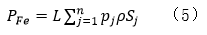
In the formula: n—the number of units of the entire iron core; L —the length of the stator core (m); p —the density of the silicon steel sheet (kg/m 3 ); S j —the area of the jth unit (m 2 ); p j — Core loss per unit mass of unit j (W/kg).
c ) The loss of the stator core under the rotating magnetic field can be calculated as follows:

In the formula: T—magnetic field change period (s); B x , By y —X, Y magnetic density amplitude (T)
d ) Stator core loss calculation considering harmonic magnetic field:
Based on the calculation results of the previous formula, the radial flux density component and the tangential flux density component waveform of each feature point on the stator core are respectively subjected to Fourier transform, and then according to the results of the FFT transformation of the flux density component at each point, each time Substituting the flux density amplitude of the harmonic into the following formula, the iron loss of the stator under the joint influence of the rotating magnetic field and the harmonic can be obtained.
e ) Traditional core loss calculation is carried out according to the following formula:
In the formula: P 10/50 — the loss (W/kg) produced by silicon steel sheet per unit mass when B=1T , f=50Hz ; G —the mass of stator core (kg); k —empirical coefficient.
6.9.2 Calculation of rotor core loss
Compared with the iron loss of the stator, the eddy current loss generated by the permanent magnet and the rotor iron core is relatively small. At present, formula calculation method or finite element analysis method can be used to calculate the eddy current loss in the rotor and permanent magnet. Using the formula to calculate the eddy current loss is not only complicated, but also has low accuracy. It is difficult to take into account many characteristics of some ferromagnetic materials. The actual design generally uses finite element analysis to obtain the eddy current loss value.
6.9.3 Calculation of winding copper loss and mechanical loss
a ) Winding copper loss can generally be divided into basic copper loss and additional copper loss. The basic copper consumption expression is as follows:
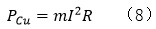
In the formula: m —the number of phases of the motor, generally m=3 ; I —the effective value of the winding phase current (A); R —the effective resistance value of each phase winding (Ω). Additional copper consumption is negligible.
b ) Mechanical loss mainly refers to friction loss caused by bearing friction and wind wear loss caused by friction between rotor rotation and air. Friction loss is generally small and can be ignored. The wind loss of the rotor is determined by the following formula:
In the formula: a — surface roughness of rotor core, a=1 when the surface of rotor core is smooth ; C f — coefficient of friction; p 0 — density of surrounding gas (kg/m 3 ); w m — angular velocity of rotor rotation (rad/s); r —rotor radius (m); L —rotor axial length (m). Where C f can be calculated as follows:
where Re δ and Re ea are the radial Reynolds number and tangential Reynolds number, respectively. The radial Reynolds number R e δ is related to the air gap length of the motor, rotor material and speed, etc.:
In the formula: δ - the length of the air gap (m); u - the relative permeability of the rotor material.
The tangential Reynolds number R e δ is related to the properties of the surrounding air:
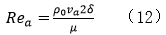
In the formula: v a ——viscosity coefficient (P) of the surrounding gas.
7 Structural Design
7.1 Basic content of structural design
( 1 ) Determine the overall structural type of the motor, including protection type, bearing type and number, shaft extension type, installation method, cooling method, shaft current protection structure, etc.;
( 2 ) Determine the structural type, material, shape, size, machining accuracy, shape and position tolerance, surface roughness and technical requirements of the parts;
( 3 ) Determine the mechanical connection mode and type of cooperation between certain parts;
( 4 ) Check the mechanical properties of the simulated parts, including strength and stiffness calculations.
7.2 Structural Design Principles
( 1 ) It should be ensured that the motor can run safely and reliably within the specified period, and the strength of the shell should meet the requirements of the vehicle under different working conditions;
( 2 ) All structural types shall comply with relevant national standards;
( 3 ) Try to make the parts conform to "standardization, serialization and generalization";
( 4 ) It should have good structural manufacturability;
( 5 ) The convenience of motor disassembly and maintenance should be considered;
( 6 ) Pay attention to the beautiful appearance.
7.3 Housing design
The motor housing includes the casing, front / rear end cover, rear cover, junction box and other components.
7.3.1 Design requirements
The motor housing should have sufficient strength and rigidity to allow the motor to run safely and have sufficient strength and rigidity.
The chassis design is mainly designed for water channel heat dissipation, which needs to meet the heat dissipation requirements of the whole machine. The type of cooling water channel can be selected from spiral water channel, axial water channel or circular water channel according to the manufacturing process and cost evaluation.
The design of the front and rear end covers requires good assembly compatibility with the casing and sufficient strength to support the rotor. During die-casting manufacturing, some other metals or non-metals can be cast into die-castings to make them have special properties and uses.
7.3.2 Design steps
( 1 ) Select the overall structural form and materials used for the motor, and draw a structural sketch.
( 2 ) According to the shape and size of the effective part of the motor determined in the electromagnetic calculation, for example, from the inner and outer diameters of the stator and rotor cores, the axial length of the core and the length of each stack of cores, the stator and rotor cores can be drawn, and the winding ends can be calculated After the part is stretched, according to the requirements of electrical clearance, creepage distance, allowable outer limit and installation size, etc., draw the model of the casing and end cover.
( 3 ) According to the general assembly drawing, draw the component assembly drawing, that is, draw each component (such as stator, rotor, bearing, etc.) separately, specify certain dimensions, and propose the matching level, tolerance requirements and technical requirements of the mating surface .
( 4 ) Further specify the shape and size of each part (except standard parts) in each component, determine all processing dimensions and tolerances, processing accuracy, surface roughness, and propose technical requirements for non-standard materials, etc., to form parts Processing diagram.
( 5 ) Check and calculate the mechanical performance: the stress of the shell and the size of the corresponding deformation generated must not exceed the allowable stress of the material used, and there will be no deformation that endangers the assembly accuracy and reliable operation of the motor.
7.3.3 Shell material selection
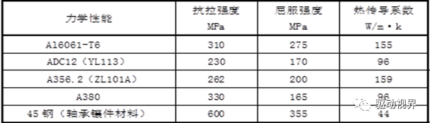
Shell material selection requires good heat dissipation performance and mechanical strength, good manufacturability, Al6061-T6 , ADC12 ( YL113 ), A356.2 ( ZL101A ) or A380 can be selected , and the material of the front and rear end cover bearing inserts is 45 steel Or cast iron, the performance parameters are as follows.
Table 1 Reference table of mechanical properties of shell materials
7.4 Shaft design
The motor shaft should be able to meet the maximum torque output requirements of the vehicle under various working conditions. The mechanical strength of the motor shaft depends on optimized structural design, accurate force analysis and verification, material selection, heat treatment and processing and assembly. If necessary, static torque test and torsional fatigue test shall be carried out.
7.4.1 Shaft Design Requirements
The shaft requires sufficient strength, sufficient stiffness, and deflection within the allowable range; sufficient fatigue strength; the critical speed is far away from the working speed, and the modes of each order are as high as possible.
7.4.2 Shaft material selection
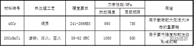
According to the design requirements of the shaft, in addition to sufficient strength, stiffness, and fatigue strength , the material of the shaft needs to be easy to process, and have good wear resistance and impact toughness. For example, 20CrMnTi material is usually used in spline shaft design. It is a carburizing steel with good performance and high hardenability. After carburizing and quenching, it has a hard and wear-resistant surface and a tough core, and has high low-temperature impact toughness. , medium weldability, good machinability after normalizing, 40Cr material is generally used for stepped shaft design, performance parameters are shown in the table below.
Table 2 Reference table of mechanical properties of shaft materials
7.5 Stator and rotor stamping design
7.5.1 Stator and rotor stamping design requirements
The stator and rotor punching plates of the motor need to be optimized according to the combination of magnetic circuit simulation and mechanical strength simulation. At 1.2 times the maximum operating speed, the mechanical strength of the punching plate is checked by CAE simulation, and the influence of high temperature is considered. The allowable stress should meet the requirements of the material mechanical strength safety factor , and ensure that the rotor deformation is less than 10% of the air gap length .
7.5.2 Type selection of stator and rotor punching materials
The motor stator and rotor core materials constitute the motor magnetic circuit. The selection of the material can greatly affect the motor stator and rotor size, motor power density, motor iron loss and motor efficiency. The selection of ultra-thin and highly saturated silicon steel sheets And use is one of the important ways to improve the motor power volume ratio and power density, and improve the efficiency of the motor. The stator and rotor core materials of electric vehicle permanent magnet synchronous motors should meet the following requirements:
( 1 ) The silicon steel sheet must have a high magnetic induction to provide high torque for starting;
( 2 ) Silicon steel sheet has high magnetic induction under medium and low magnetic field and low iron loss under high frequency to improve energy conversion efficiency;
( 3 ) At high speed, the silicon steel sheets used are required to have high strength, especially for permanent magnet drive motors, where the magnetic poles are embedded in the rotor, so it is very important to ensure the strength of the rotor;
( 4 ) It is required that the silicon steel sheets used have good punching properties and reduce the gap between the rotor and the stator, thereby effectively increasing the magnetic flux density;
( 5 ) High fatigue life.
For electric vehicle permanent magnet synchronous motor stator and rotor core materials, please refer to the comparison table of magnetic properties of non-oriented silicon steel sheets of different models and thicknesses shown in the table below.
Table 3 Comparison table of magnetic properties of cold-rolled non-oriented silicon steel sheet
7.6 Permanent magnet design
( 1 ) Permanent magnet design requirements : In the design of permanent magnet synchronous motors, permanent magnet materials are required to have high surface remanence, high intrinsic coercive force, high magnetic energy product and good temperature stability. The shape of the permanent magnet is usually designed as a rectangle, and the axial length of the permanent magnet is the same as the length of the rotor core. It is necessary to determine the total width of the permanent magnet of each pole and the length of the magnetization direction of the permanent magnet.
The principle of determining the length of the magnetization direction of the permanent magnet: on the premise that the amount of the permanent magnet is as small as possible, the electromagnetic simulation is used to ensure that irreversible demagnetization will not occur under the maximum demagnetization working state of the motor, and to ensure that the permanent magnet works reasonably under steady-state operating conditions point.
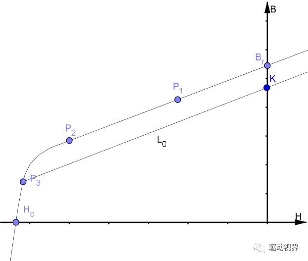
Figure 2 Irreversible nonlinear demagnetization model
( 2 ) Selection of permanent magnet materials : NdFeB materials are generally used as permanent magnet synchronous motor materials for automobile drives, which have the advantages of small size, light weight, high remanence, high coercive force and high magnetic energy product. Through electromagnetic design simulation, comprehensive motor torque density, torque ripple, motor loss, motor efficiency and motor operating temperature stability, select the appropriate permanent magnet material, according to the corresponding parameters of the major permanent magnet manufacturers (such as Zhongke Sanhuan, Zhenghai magnetic materials, etc.).
8 thermal design
( 1 ) Design content: determine the cooling method, determine the flow rate of the cooling medium, calculate the flow resistance, flow distribution and pressure difference of the cooling circuit, calculate the thermal resistance of the thermal circuit, and calculate the temperature rise and temperature distribution of various places according to the relevant working conditions: 1) Rated working conditions 2 ) Peak conditions are calculated based on the continuous running time of 30s .
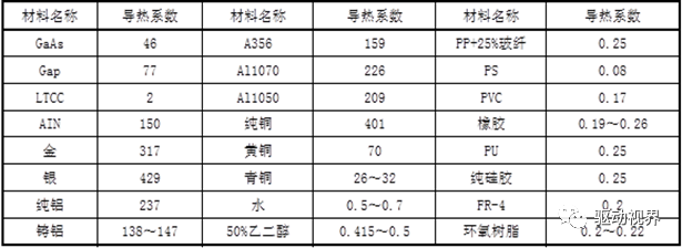
(2) Thermal conductivity of commonly used materials : Thermal conductivity is a parameter index that characterizes the thermal conductivity of materials. It indicates the heat conduction per unit time, unit area, and negative temperature gradient. The unit is W/mK or W/mC. Commonly used materials The thermal conductivity is shown in the table below.
Table 4 Thermal conductivity table
9 insulation design
9.1 Insulation design requirements
9.1.1 Insulation resistance
( 1 ) Cold-state insulation resistance: the cold-state insulation resistance value of the motor stator winding to the casing ≥ 20MΩ ; the cold-state insulation resistance value of the motor stator winding to the temperature sensor ≥ 20MΩ ; the cold-state insulation resistance of the resolver to the motor stator winding ≥ 20MΩ .
( 2 ) Insulation resistance in hot state: The motor should have sufficient insulation resistance value at room temperature, hot state and after being exposed to moisture. The cold state insulation resistance value of the motor stator winding to the casing and the motor stator winding to the temperature sensor should not be lower than Value calculated as follows:

R: the cold state insulation resistance value of the motor stator winding to the casing, and the motor stator winding to the temperature sensor; U dmax : the highest working voltage, unit (V); P: continuous power of the motor, unit kW; insulation resistance calculated according to the above formula When it is lower than 1 MΩ , it is recommended to press 1 MΩ .
9.1.2 Power frequency withstand voltage
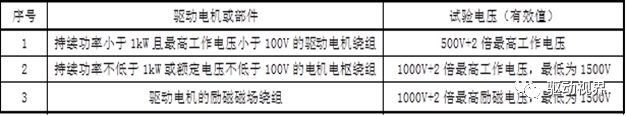
The power frequency withstand voltage of the motor stator winding to the temperature sensor should be able to withstand the power frequency withstand voltage of AC1500V , without breakdown phenomenon, and the leakage current limit is ≤5mA . The motor windings should be able to withstand the power frequency sinusoidal withstand voltage test specified in the table below, without breakdown, and the leakage current limit is ≤10mA .
Table 5 Power frequency withstand voltage limit table of motor winding to casing
9.2 Requirements for insulating materials
During the use of motor insulation materials, under the long-term effects of various factors, the insulation performance will be reduced or even lost due to electrical breakdown, corrosion, natural aging, mechanical damage and other reasons. After the motor design is completed, it must be ensured that the motor has good electrical properties, mechanical properties, heat resistance and chemical resistance.
( 1 ) Electrical properties: The electrical properties of insulating materials mainly include dielectric strength, volume and surface resistance, dielectric constant, dielectric loss tangent, arc resistance, tracking resistance, corona resistance, discharge intensity along the surface, Various characteristic frequency coefficients, etc. When designing the insulation structure, the electrical properties of the selected materials should be fully understood so that the electrical properties of the materials can meet the requirements. When designing motor insulation, the dielectric strength of the insulating material is mainly considered.
( 2 ) Mechanical strength: The mechanical properties of insulating materials mainly include strength such as tensile, compressive, and shear strength, and the insulating material is required to have sufficient mechanical strength.
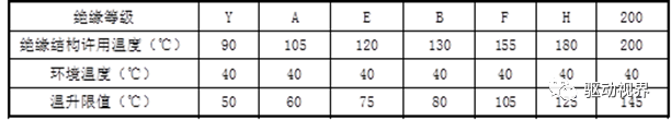
( 3 ) Heat resistance: The thermal performance of insulating materials is reflected by heat resistance. Heat resistance means that insulating materials can be exposed to high temperature and rapid changes in temperature for a short or long time without damage or deterioration of their important properties. Ability. Heat resistance is usually the factor that has the main influence on the aging of insulating materials and insulating structures. In the electrical insulation structure or insulation system of motors, it is classified according to the heat resistance grade. Insulation materials are generally divided into seven heat resistance grades: Y , A , E , B , F , H , 200 and above. The insulation grade of driving motors for automobiles needs to reach H grade or above.
( 4) Chemical resistance: the stability and compatibility of the chemical properties of insulating materials to environmental conditions.
a ) Stability needs to consider the harmful effects of insulating materials on the surrounding environment, such as toxic, flammable, explosive and corrosive, etc.;
b ) The various insulating materials used in the insulating structure require excellent compatibility with each other. This compatibility means that when two or more insulating materials are used in combination, their functions will not be due to chemical, physical or both. Some factors cause unfavorable mutual influence, and the compatibility of insulating materials directly affects the life of electrical insulation structures.
Table 6 Insulation class and temperature rise limit table
9.3 Selection of insulating materials
Motor insulation includes stator slot insulation, stator layer insulation, stator end turn-to-turn insulation, ground insulation and magnet wire insulation, etc. For the selection of insulation materials for automobile drive motors, the temperature resistance level must meet the requirements of H level and above.
( 1 ) Stator slot insulation generally uses NHN ( N is polyaramid fiber paper, H polyimide film) insulating paper with a thickness of 0.35mm or more, and impregnating varnish and other auxiliary materials also use corresponding H- grade materials;
( 2 ) NHN insulating paper with a thickness of 0.2mm is used for stator interlayer and interturn insulation ;
( 3 ) Winding insulation sleeve: use 2751 silicone rubber glass paint tube ( H -level insulation) and 2750 silicone glass paint tube ( H -level insulation);
( 4 ) The requirements for the insulation of the magnet wire are mainly heat resistance and mechanical properties. The insulation requires dielectric properties and mechanical properties, and the impregnated paint requires bonding strength, etc. The type of round magnet wire for the motor is selected:
a ) Water-cooled magnet wire: composition PE+AI, 200-grade polyamide-imide enamelled round copper wire (GB/T6109.14-2008);
b ) Oil-cooled magnet wire: general composition AI, 220 polyimide enamelled round copper wire (GB/T6109.6-2008).
( 5 ) Winding insulation treatment methods: varnish dipping and potting, among which varnish immersion is the most common, and insulation treatment is a special process that requires necessary process verification;
( 6 ) For automotive permanent magnet synchronous motor seals such as seal rings, seal rubber pads and oil seals, the temperature resistance of the seals should be above 150°C .
9.4 Busbar design
Electrical safety design: The electrical clearance and creepage distance between the busbar and each component should comply .
Table 7 Busbar Clearance and Creepage Distance Selection
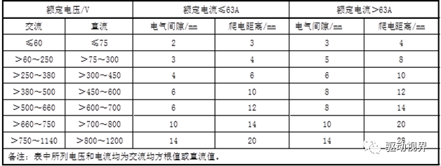
The rated current of the busbar refers to the specified limit in the table:
Table 8 Selection of busbar rated current
10 Bearing selection
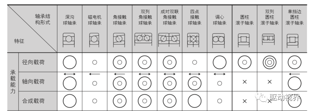
Automotive permanent magnet synchronous motor bearings are required to have good high temperature performance, low temperature performance, low noise and long life. The bearing type selection is comprehensively carried out according to the load type of the motor, the limit speed, the installation space, and the service life requirements.
(1) Select the bearing type according to the load bearing type of the bearing. The load types mainly include radial load, axial load and composite load. The load bearing capacity of various bearings can refer to the following table:
Table 9 Comparison table of load bearing capacity of various types of bearings
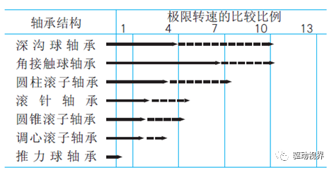
( 2 ) According to the requirements of the maximum operating speed of the motor, select the bearing type whose limit speed meets the requirements. The comparison ratio of the limit speed of each type of bearing can refer to the table below.
Table 10 Comparison table of limiting speed of various bearings
( 3) Refer to the figure below to select the appropriate bearing size according to the bearing space requirements.
Figure 3 Reference chart of various bearing size series
( 4 ) The rated life of the bearing is calculated and checked with reference to GB/T 6391-2010 "Rated Dynamic Load and Rated Life of Rolling Bearings" or checked according to the life calculation method recommended by the bearing manufacturer.
( 5 ) According to the internal environmental requirements and temperature resistance requirements of the motor, select the bearing temperature resistance level requirements, sealing method, and lubrication method, such as grease lubrication or oil lubrication;
( 6 ) Select the rotation accuracy of the bearing according to the requirements of rotation accuracy, high-speed rotation and torque variation;
( 7 ) Select the structural shape and material of the bearing cage according to the noise requirements, operating temperature, external vibration and impact of the motor;
( 8 ) Select the clearance level of the bearing according to the requirements of noise, speed and fit accuracy;
( 9 ) Select the structural form of the bearing according to the ease of installation and disassembly, and whether the inner and outer rings are separable.
11 Resolver selection
11.1 Selection requirements
The number of pole pairs of the motor is an integer multiple of the number of pole pairs of the resolver, and the type is selected according to the following performance parameters:
( 1 ) Rated excitation voltage and excitation frequency: the excitation voltage adopts a relatively low value, generally below 10V . The excitation frequency of the drive motor resolver is generally 5 ~ 10kHz .
( 2 ) Transformation ratio and maximum output voltage: The transformation ratio refers to the ratio of the output voltage to the excitation voltage of the primary side when the output winding is at the position where the maximum output voltage is induced.
( 3 ) Electrical error: The output electromotive force and the rotation angle should conform to a strict positive and cosine relationship. If they do not match, an error will occur. This error angle is called an electrical error. The accuracy grade of the resolver is determined according to different error values. Different resolver types achieve different levels of accuracy.
( 4 ) Impedance: Generally speaking, the impedance of the resolver changes with the angle, which is related to the mutual angular position between the primary and secondary, and a specific position should be taken when measuring. There are 4 impedances: open-circuit input impedance, open-circuit output impedance, short-circuit input impedance, and short-circuit output impedance.
( 5 ) Phase shift: In the case of secondary open circuit, the phase difference of the secondary output voltage relative to the primary excitation voltage in time. The magnitude of the phase difference varies with the type, size, construction and excitation frequency of the resolver.
( 6 ) Zero voltage: The point where the same-phase component of the fundamental wave of the output voltage is zero is called electrical zero, and the voltage at this time is called zero voltage.
( 7 ) Reference electrical zero position: The electrical zero point determined as the reference point of the angular position is called the reference electrical zero position.
11.2 Resolver Assembly Requirements
( 1 ) The center of rotation between the stator and the rotor must be consistent to ensure that the change law of the air gap magnetic field is strictly in accordance with the theoretical value;
( 2 ) The axial center lines of the stator and rotor coincide.
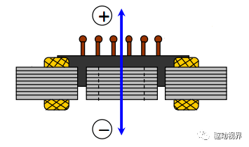
▲ Axial
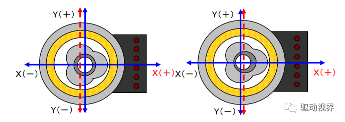
▲ Radial
Figure 4 Resolver eccentricity
( 3 ) When assembling, it cannot be too tight or too loose, and cannot be hit with a hammer to avoid deformation and damage;
( 4 ) Apply rated power supply voltage: All parameters of the resolver are measured at the rated voltage. If the applied voltage is too large or too small, it will affect the performance and application to a certain extent;
( 5 ) Shielding: When there is a strong external magnetic field close to the resolver, it will affect the resolver magnetic field and the magnetic field at the end of the winding, thereby generating an error potential and causing an error to the resolver. When assembling, keep away from strong magnetic fields, and take magnetic shielding measures to prevent interference;
( 6 ) Wiring is correct: Wiring according to the specified marks, the sine phase, cosine phase and positive direction of excitation cannot be wrongly connected.
 XINDA
XINDA