


E-axle design overview v1
one
Overview and definition of electric drive axle
two
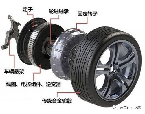
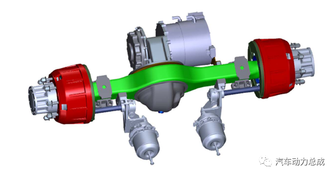
Classification of electric drive axle
three
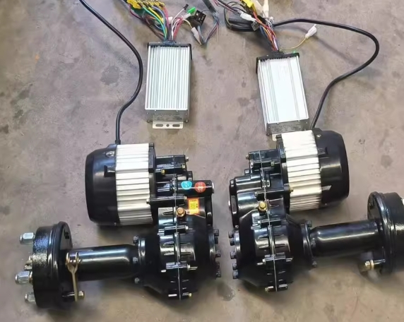
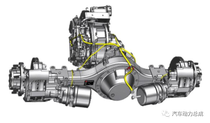
Design of Integral Electric Drive Axle
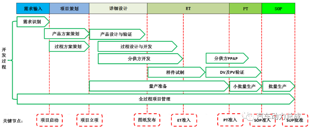
The development process of the electric drive axle project is generally carried out according to the standard process of auto parts development as shown in the figure below. The following takes the parallel shaft integral electric drive axle as an example to mainly explain the detailed design process and method of the electric drive axle.
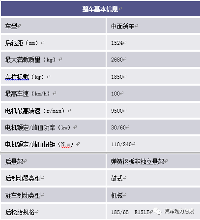
Before an electric drive axle project starts, the market research or the customer directly specifies the requirements, and the input to the R&D department includes the basic information of the vehicle, product performance, size boundaries, and project nodes. For example, the table below shows the basic information of a new energy van logistics vehicle.
Taking this new energy vehicle as an example, the basic design method of each component system will be explained in the following.
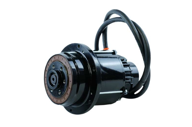
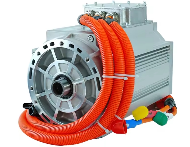
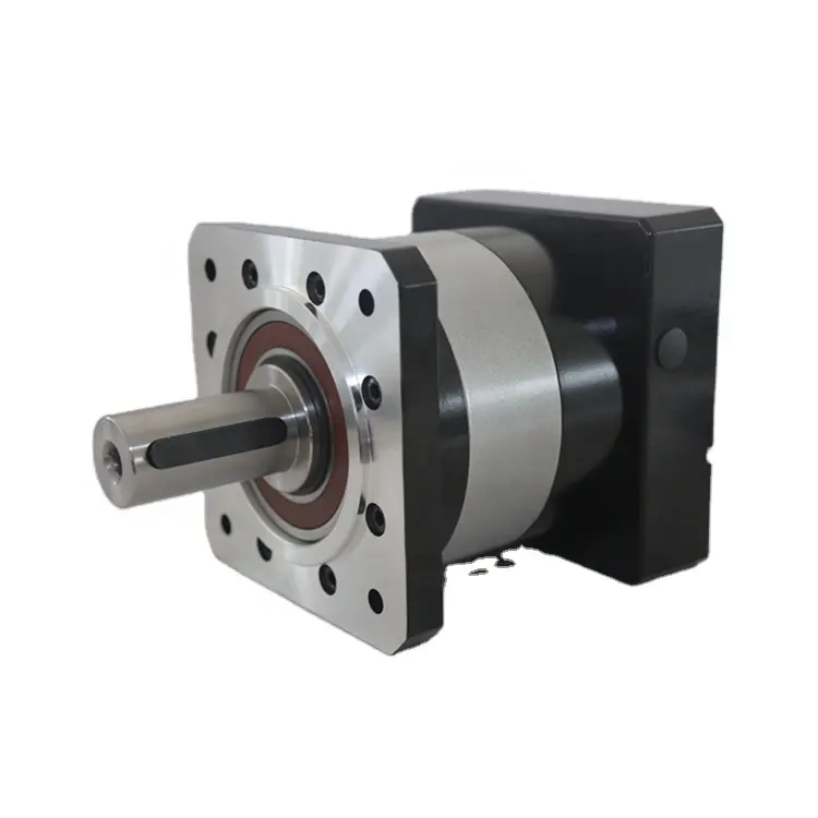
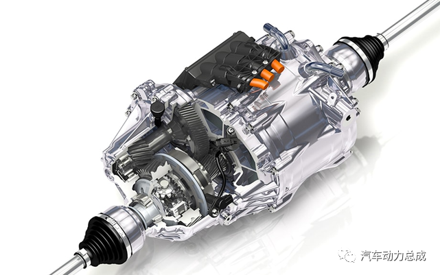
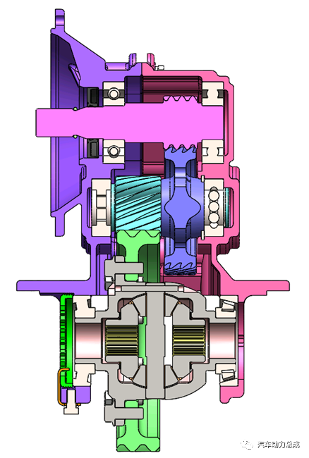
As the core component of the electric drive axle, the reducer assembly should be focused on in the design stage. Due to the short battery life of pure electric vehicles and the high input speed caused by the current trend of high-speed motors, compared with traditional fuel vehicle transmission (reduction) gearboxes, electric vehicles propose high efficiency, high torque density, and High reliability and high NVH performance, and simple structure and other requirements.
At present, most reducer products adopt single-speed design, which generally adopts two-stage cylindrical helical gear reduction, mainly composed of two-stage gear pairs, bearings, differential assembly, reducer case and oil seal and other structures.
Because the degree of coincidence has a key influence on the meshing noise of the gears, almost all cylindrical helical gears used in automotive gearboxes currently use a thin and high-tooth tooth profile design.
It is generally required that the coincidence degree of the end faces of the first-stage gear pair is 2 or as close as possible, especially avoiding that it is close to x.5 (x is any integer), and the axial coincidence degree is also as close to an integer as possible, and the total coincidence degree is at least 4; Low, the coincidence degree of the end face can be appropriately reduced to 1.8+, and the coincidence degree of the axial direction is close to an integer.
Because the tooth shape of thin and high teeth becomes sharper, attention should be paid to the tooth tip width during the gear design process to avoid tooth tip hardening during the gear heat treatment process.
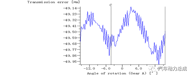
Calculating the meshing error of the gear pair needs to consider the influence of the stiffness of all components, including the basic properties, clearance and fit relationship of the reducer case, gear shaft, and bearings. It is generally required that the first stage PPTE of the gear pair≤0.4, and the second stage PPTE≤0.7. For its harmonics of each order, it is also necessary to decrease step by step.
Using KISSsoft software as an example to calculate, select the parameters of the gear pair according to the above basic principles of the gear pair, and check the results of the gear strength, coincidence degree and meshing error analysis as shown in Figures 3 and 4.
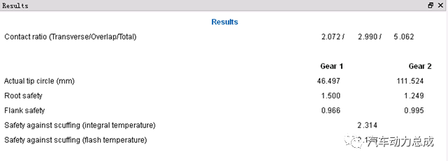
Figure 3 Strength check of first-stage gear pair
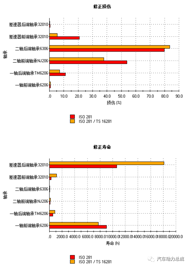
After the parameters of the gear pair are determined, the bearing can be selected according to the force state of the gear pair. After the selection is completed, the force is decomposed and the equivalent load of the bearing is calculated to check its life. After the bearing life requirements are determined according to the load spectrum of the vehicle, the damage rate generally cannot exceed 80%, the contact stress of the ball bearing raceway should not exceed 4000MPa, and the roller bearing should not exceed 4200MPa.
In the case of meeting the service life, it is necessary to increase the input speed of the reducer assembly and reduce the friction torque of the system. Generally, low rolling resistance bearings such as ball bearings are given priority.
After the gear pair and bearing are determined, the reducer box can be designed, and the impact on NVH and its dynamic stiffness should be considered in the box design. The first-order free mode of the box is recommended to be above 1500Hz, and the first-order constrained mode is above 700Hz; the dynamic stiffness of each position (bearing hole, mounting point, etc.) must be greater than 20000N/mm, and the thin-walled large-plane structure should be minimized. If the follow-up capability permits, carry out resonance and frequency response simulations and tests for frequency regions with large vibration radiation.
In terms of structure, it is necessary to consider the space layout requirements and assemblability of the vehicle, improve assembly efficiency and precision, and focus on lightweight.
Due to the current high speed trend of motors, the requirements for the sealing performance of the reducer input shaft oil seal are getting higher and higher, low friction and high temperature resistance. The current solution is to improve the performance of the oil seal lip material, often using FPM (fluorine rubber), or even PTFE (polytetrafluoroethylene) and other rubber materials. The diameter of the shaft matched with the oil seal should be reduced as much as possible without affecting the strength and stiffness, and the surface of the matched shaft should be finely ground or polished without axial feed, and the surface roughness should be at least ≤ Ra0.4 to improve the life of the oil seal.
When the torque and assembly requirements are met, the planetary gear and the side gear adopt a small thrust clearance (0.05-0.15) mm to reduce the clearance of the transmission system, avoid tooth surface impact and other phenomena, and improve NVH performance.
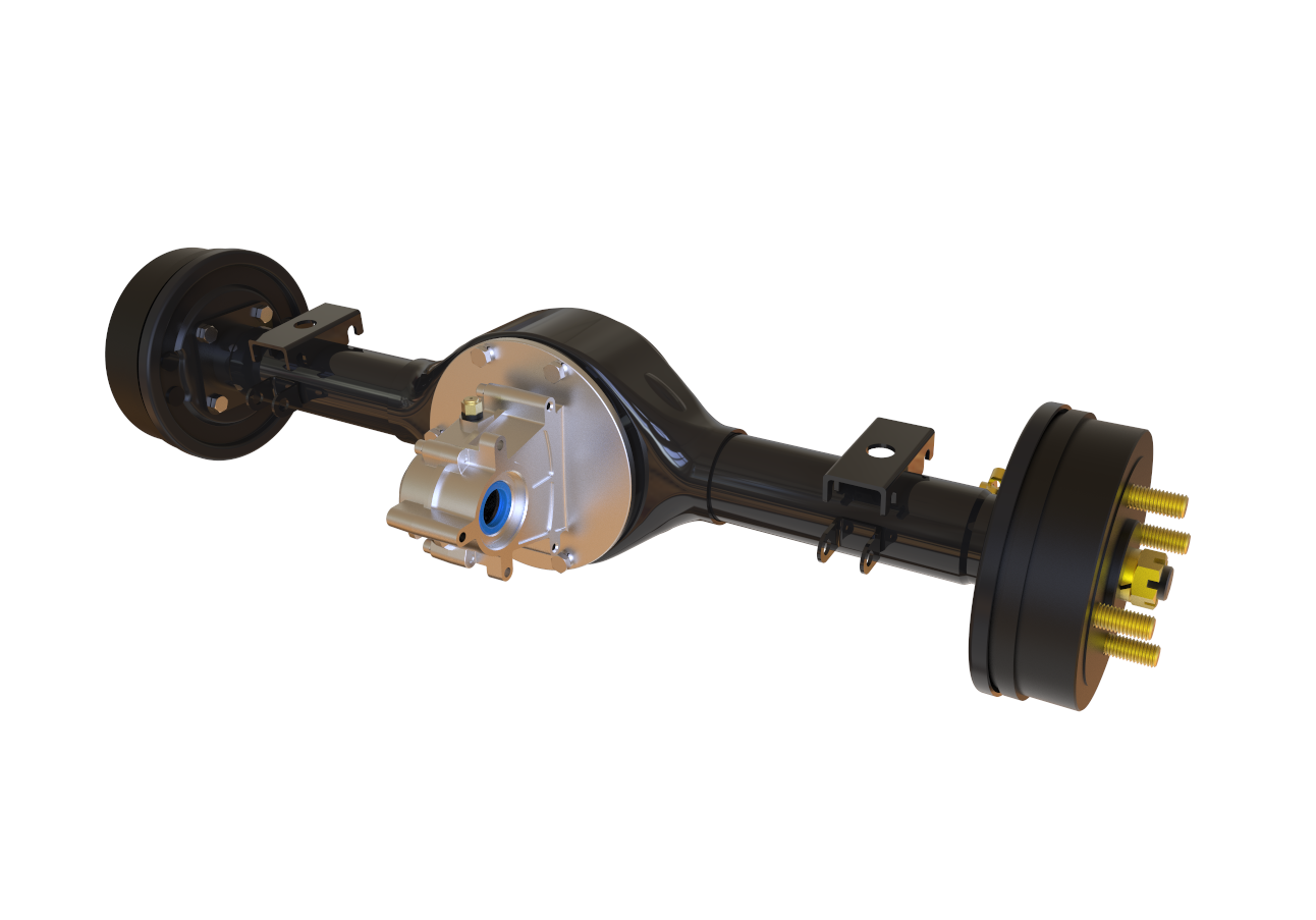
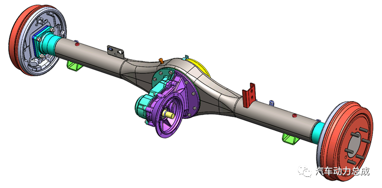
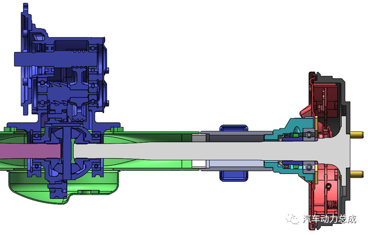
The axle housing assembly is mainly responsible for bearing, transmitting force and moment. It is a critical part and requires a high safety factor. At present, most of the integrated electric drive axle housings borrow the original fuel vehicle axle structure, which is mature and widely used.
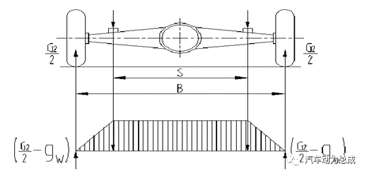
The calculation and checking method of axle housing and axle shaft generally refers to "Automobile Axle Design" written by Liu Weixin.
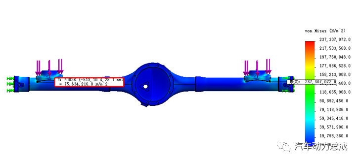
The axle housing mainly plays the role of bearing and supporting, and is a hollow beam structure. When designing, it is necessary to consider the impact coefficient according to different models and road conditions, calculate and check its bending strength, stiffness and fatigue, and conduct bench tests in accordance with GB/T533 and 534 to ensure that the simulation and test results are consistent (see Figures 6 and 7).
At present, stamped and welded axle housings are widely used because of their high material utilization and light weight .
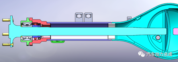
There are full-floating half-shaft, semi-floating half-shaft and 3/4 type (less used). The force and moment transmitted by the two structures are different: the full-floating half-shaft only needs to check its torsional strength and fatigue ; The formula needs to add bending moment check on its basis. After the design is completed, carry out the bench test according to GB/T 293 and 294.
It is divided into full-floating axle and semi-floating axle: the full-floating axle needs to check the life of its hub bearing according to the load spectrum and working conditions, and at the same time design the axle hub according to the installation size requirements of the rim and conduct CAE analysis; semi-floating axle The formula needs to check the life of the half shaft bearing.
The brake system design is generally based on the vehicle parameters or the requirements of the OEM, matching the brake type and calculating its braking torque to meet the vehicle braking requirements.
4
Engineering Verification and Test
After the detailed design is completed, the first round of prototype trial production and DV test will be carried out to verify the feasibility of the design scheme and adjust and optimize the scheme according to the trial production process and test results
5
Production verification and SOP
According to the optimization of the first round of test results, the second round of small batch trial production and PV test will be carried out to verify the feasibility of production and complete the pre-batch production preparation.
 XINDA
XINDA