


Electric vehicle motor control working principle and optimization scheme
The three electrics of new energy vehicles refer to: power battery, drive motor, and vehicle electronic control.
Three electric vehicles are the core of new energy vehicles. In the development of power battery technology, new technologies and new hot spots appear from time to time. In the field of electronic control, our development has been at a relatively early stage.
The improvement of electronic control efficiency can significantly improve the vehicle economy of pure electric vehicles.
Electronic control, in a broad sense, includes vehicle controller, motor controller and battery management system.
This paper introduces the working principle and optimization scheme of motor control.
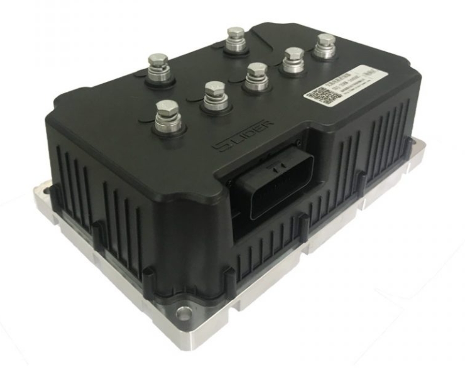
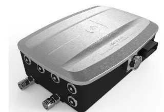
01. Motor controller
The motor controller is the nerve center connecting the motor and the battery. It is used to adjust various performances of the vehicle. A sufficiently intelligent electronic control can not only ensure the basic safety and precise control of the vehicle, but also allow the battery and the motor to exert their full strength.
' fill='%23FFFFFF'%3E%3Crect x='249' y='126' width='1' height='1'%3E%3C/rect%3E%3C/g%3E%3C/g%3E%3C/svg%3E)
02. The working process of the motor controller
The core of the motor controller unit is the control of the drive motor. The provider of the power unit - the power battery provides direct current, while the drive motor needs three alternating currents. Therefore, what the electronic control unit needs to achieve is a process called inverter in power electronics technology, that is, to convert the DC power at the power battery terminal into AC power at the motor input side.
In order to realize the inverter process, the electronic control unit needs DC bus capacitors, IGBT and other components to work together. When the current is output from the power battery terminal, it first needs to pass through the DC bus capacitor to eliminate the harmonic component, and then, through the control of the IGBT switch and the cooperation of other control units, the DC power is finally converted into AC power, and finally used as the power motor. Input Current. As mentioned above, by controlling the frequency of the three input currents of the power motor and cooperating with the feedback values of the speed sensor and temperature sensor on the power motor, the electronic control unit finally realizes the control of the motor.
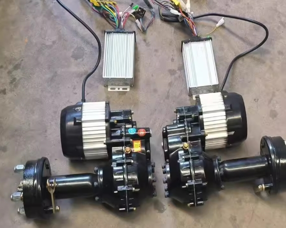
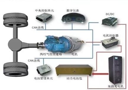
The figure below is a typical pure electric vehicle power system electrical diagram, in which the blue line is a low-voltage communication line, all communications, sensors, low-voltage power supply, etc. must be drawn out through this low-voltage connector, connected to the vehicle controller and power battery management system.
The red line is the high voltage power line. Two pairs of high voltage connectors. A pair of input interfaces are used to connect to the high-voltage interface of the power battery pack; the other pair are high-voltage output interfaces, which are connected to the motor to provide control power.
The difference in the working principle of the motor directly affects the complexity and accuracy of the regulation process.
Arranged from easy to difficult according to control, they are brushless DC motors, permanent magnet synchronous motors, switched reluctance motors, and asynchronous motors.
The difficulty of electronic control includes not only the size and cost of the hardware system design, but also the control accuracy achieved by the software algorithm and the robustness of the strategies and methods used to achieve this accuracy.
What people expect is a control system with simple hardware structure, simple software algorithm, high control precision and good system stability.
03. Motor controller main circuit selection
Selection basis: The motor controller is an inverter with specific functions. It uses the voltage regulation and frequency modulation technology in power electronics technology to modulate the direct current stored in the power battery into the rectangular wave or sine wave alternating current required to control the motor. , change the voltage, current amplitude or frequency of the output power, and then change the motor speed and torque to achieve the purpose of controlling the speed and acceleration of the vehicle.
In the design of power electronic circuits, according to different speed regulation requirements, designs with different degrees of complexity and different costs are made.
For example for the control of DC motors. If a single-tube chopper circuit is used, the speed can only be adjusted in one direction, and the current cannot be reversed; if a double-tube chopper circuit is used, energy feedback can be realized, but the DC motor cannot be commutated; if an H-bridge type is used The chopper circuit can adjust the speed of the DC motor, can feed back energy, and can reverse the excitation current.
However, among the above three options, one is more complicated than the other, and the cost is higher than the other. Designers need to make a choice between performance and cost. The most expensive is not necessarily the best, but the most suitable one is good.
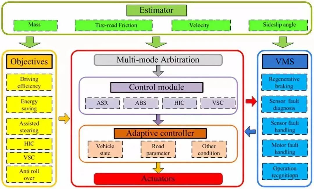
04. Distributed drive electric vehicle integrated control
Distributed drive electric vehicles have the advantages of good controllability, short transmission chain, compact structure, and high utilization of interior space, which have always been the focus of research and development. Moreover, the driving motors of each wheel can be independently controlled. Through the reasonable distribution of the motor torque, the high-efficiency range of the motor can be fully utilized, combined with the feedback braking strategy, the economy of the vehicle can be improved.
In order to improve the adaptability of the control system to the vehicle parameters, state and vehicle driving environment, it is necessary to design a state estimation and parameter identification algorithm that meets the control requirements, and at the same time ensure the stability of the control-estimation system, and the distributed drive provides the vehicle state estimation algorithm. Bigger possibility.
In order to ensure the good driving performance of distributed drive electric vehicles under complex working conditions, and to solve the coordination problems of multi-control targets, multi-control functions, multi-actuators and multi-dimensional motion, integrated control has become the current research on the dynamic control of distributed drive electric vehicles. focus.
Traditionally, independently designed controllers have their own clear control objectives. However, there is a certain degree of functional overlap and interference among the various systems. Therefore, the action distribution of multiple execution systems and the coordination of multiple control objectives are the key to the system integration control strategy.
05. Efficiency optimization technology of electronic control system
The efficiency of the electronic control system is increased by 1%, which is very advantageous for the economy and weight of the vehicle. The efficiency optimization technology includes dynamic adjustment of carrier frequency, DPWM wave generation technology, over-modulation technology, and wide-area high-efficiency HSM motor.
-
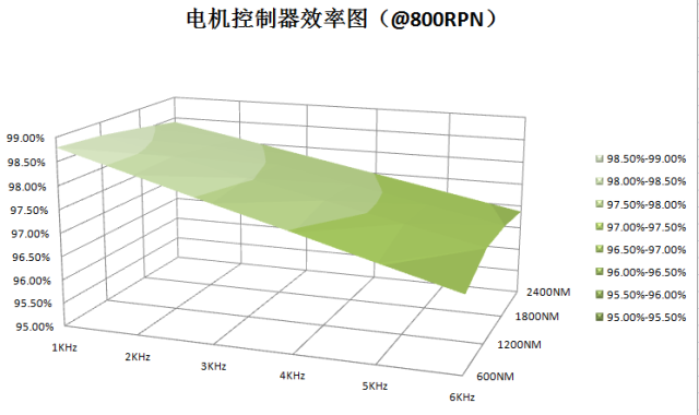
Carrier frequency dynamic adjustment technology
The main loss source of the electronic control system is the inverter part, and 70% of the inverter loss comes from the switch part.
From the point of view of switching loss reduction, the carrier frequency dynamic adjustment technology is studied. Through the simulation test, it is found that after adjusting the switching frequency, the efficiency of the controller can be increased by about 2%. Using the dynamic carrier frequency technology, especially at low speeds, when the carrier frequency is not so high, adjusting the carrier frequency can effectively reduce the controller efficiency. The loss and the efficiency of the controller are initially estimated to provide about 1.5 kilometers per 100 kilometers. The carrier frequency cannot be lowered without limit, and the needs of vehicle noise and motor control need to be considered.
-
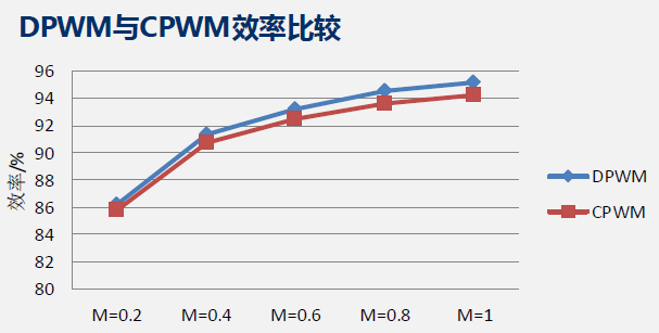
DPWM Wave Technology Application
For the technical application of discontinuous wave transmission, DPWM technology is used to reduce the switching times by 1/3 compared with COWM technology, which can significantly reduce the switching times and achieve the purpose of reducing switching losses.
When the modulation ratio M>0.816, the harmonics under CPWM and DPWM modulation are approximately the same. This area can use DPWM technology to reduce device loss.
-
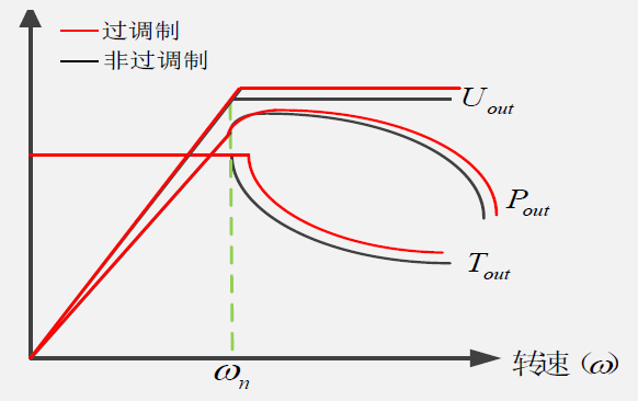
Application of overmodulation technology
Controller losses include switching losses and conduction losses. The conduction loss has a great relationship with the output current. When the output power is constant, the output voltage needs to be increased correspondingly when the output current decreases.
By adding over-modulation, the output power and output torque in the field weakening area can be effectively increased, the output voltage can be increased by 4%, and the peak power can be increased by about 4%, which can improve the dynamic performance of the vehicle at high speed;
By adding overmodulation and outputting the same power, the current will be significantly reduced, which can reduce system heat generation, improve the overload capacity of the controller, and improve the vehicle's power performance;
By adding overmodulation, the fundamental wave voltage can be effectively increased. Compared with no overmodulation, the motor efficiency can be effectively improved, the motor current can be significantly reduced (0~8%), and the efficiency improvement can effectively extend the cruising range.
-
Wide-area high-efficiency HSM motor
In addition to the improvement of electronic control efficiency, it also includes the improvement of motor efficiency.
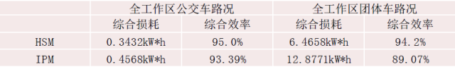
HSM motor hybrid synchronous motor, compared with IPM motor, can take into account the efficiency of low-speed area and high-speed area. Especially in the medium-high speed constant power operation area, the efficiency advantage of HSM is more obvious. The test found that in the low-speed area and high-speed area, the efficiency of HSM is higher than that of conventional IPM motors. Generally speaking, the efficiency of motors can be improved after using HSM technology.
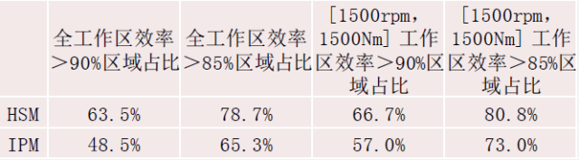
In the working conditions of buses and group vehicles, IPM motors are compared with HSM motors, and HSM motors are dominant.
Considering the comprehensive energy efficiency directional optimization technology of the whole vehicle, by adjusting the proportion of each loss component of the motor, the directional optimization of efficiency is realized. Combined with the road condition information of specific models, the motor with higher comprehensive energy efficiency is customized and developed to improve the cruising range.
06. Development trend of electric vehicle motor controller technology
-
High security, this is the basic requirement. There are more and more integrated functions, and the higher the security requirements.
-
High power density. The shape and volume develop toward miniaturization along with subpackaging.
-
High pressure is the basic trend. The direction of GBT is 650V IGBT design to higher 750V and 1200V
-
The EMC level is getting higher and higher. The next step is to achieve class5 level.
 XINDA
XINDA