


Vehicle controller VCU
1. Composition
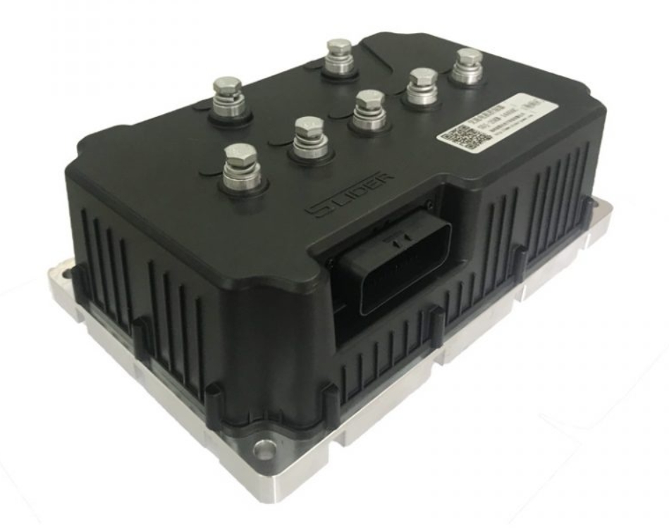
The vehicle controller is mainly composed of hardware and software. The hardware includes the housing and hardware circuits. The software is divided into application software and underlying software.
The shell is mainly used for the protection and sealing of the hardware circuit. It must meet the cleanliness requirements such as waterproof and dustproof, and also meet the mechanical requirements such as avoiding drops and vibrations.
The hardware circuit is mainly composed of a main control chip (32-bit processing chip) and peripheral clock circuits, reset circuits, and power modules. Generally, it is also equipped with digital signal/analog signal processing circuits, frequency signal processing circuits, and communication interface circuits.
Application software and underlying software are generally written in C language. The application software is mainly the upper-level control strategy, which is mainly responsible for real-time control of energy flow and distribution ratio according to the vehicle state and driver's intention. The underlying software is mainly responsible for the initialization of the microcontroller, the real-time sending and receiving of CAN bus signals, and the real-time processing and diagnosis of input and output signals.
2. Function
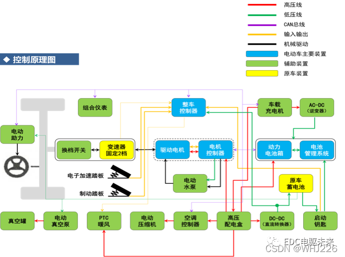
a. Drive system control
According to the driver's accelerator pedal position, gear position, brake pedal force and other operating intentions, parameters such as the torque required by the motor are calculated, and the movement of various power components is coordinated to ensure the normal driving of the electric vehicle.
b. Vehicle energy management and optimization
According to the actual working conditions, manage the vehicle, monitor the charging of electric vehicles and the recovery of braking energy, control other electrical equipment on the vehicle, realize efficient energy distribution, improve the economy of the vehicle, and prolong the service life of the vehicle.
c. Vehicle communication and network management
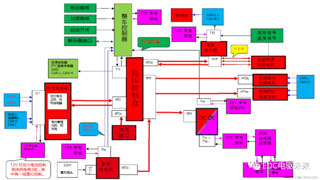
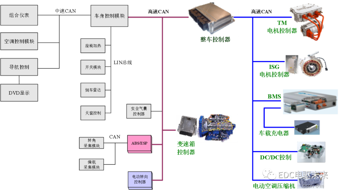
In addition to the vehicle controller, electric vehicles also have various sub-control systems such as motor controllers and battery management systems. These controllers need to communicate with each other. The vehicle controller connects each sub-control system together through the CAN communication network to coordinate Manage the entire communication network.
d. Troubleshooting and Diagnosis
Real-time monitoring of the operating status of each device, diagnosis, prompting and active repair of abnormal conditions, to ensure the safe operation of electric vehicles.
e. Car status display
Collect and process the status information of the car, and send important status and fault information to the instrument for display, such as vehicle speed, motor speed, remaining battery power, motor or battery fault information, etc.
3. Working mode
a. Self-test mode
When the key door signal is in the ON gear, start the self-test mode, the vehicle controller is powered on for self-test, if the self-test passes, it will wait for the start mode, if the self-test fails, it will enter the failure mode.
b. Start mode
The key door signal is in the START gear, and the self-test mode is passed at the same time, the vehicle controller will wake up other nodes (motor, converter, air conditioning system, etc.) After normal start, the whole vehicle enters the READY state, and the READY light is displayed on the instrument, indicating that the driver can carry out normal driving operations and complete the start-up mode.
c. Start mode
When the driver does not step on the accelerator pedal to start, the vehicle controller will coordinate the motor torque to reach the start target value, and the vehicle speed will gradually increase and be controlled within a reasonable speed range to achieve a smooth start.
d. Driving mode
During the driving process of the car, the vehicle controller collects information such as the position of the driver's accelerator pedal and the rate of change of the opening degree in real time, and controls the torque of the motor in real time according to the current driving state of the vehicle (vehicle speed, battery current, voltage, temperature, etc.) And the output power of the power battery, so as to control the operation of the car according to the driver's intention, to achieve forward, backward, cruise, acceleration, etc.
e. Brake mode
When the driver steps on the brake pedal and the car is in the braking or decelerating state, the vehicle controller calculates the required braking torque according to the current driving state of the vehicle, controls the motor to switch to the engine mode, and charges the power battery.
f. Parking mode
When the driver turns off the key, the vehicle controller controls the subsystem power supply, and after the equipment is turned off, the parking is completed.
g. failure mode
When the vehicle controller monitors that the vehicle has a failure, it will start the self-diagnosis and active repair functions, and at the same time limit the system power output, make the vehicle enter the speed limit or emergency stop state, and display the failure information to the driver.
h. Charging mode
When the charging gun is plugged in, the charging motor starts to work, and the vehicle controller will coordinate the battery management system to start charging, and continuously monitor the status of the battery management system and the charging motor, and display the charging information to the driver; when there is a failure in the charging process , the vehicle controller will cut off the battery management system relay in time to interrupt the charging process.
 XINDA
XINDA